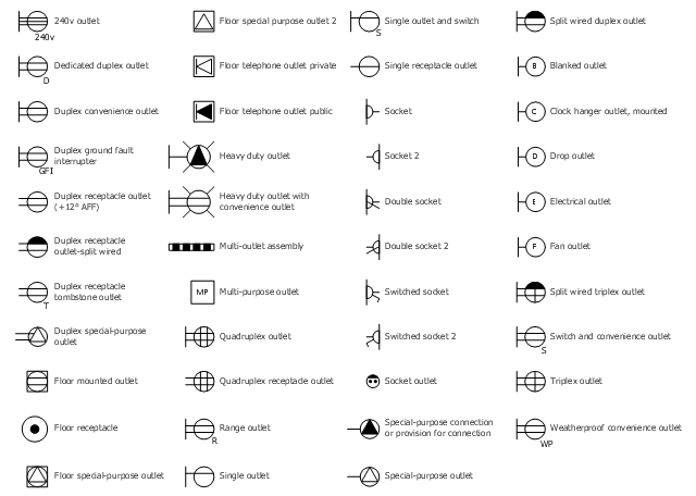
The vector stenvils library "Outlets" contains 57 symbols of electrical outlets.
Use these shapes for drawing building interior design, electrical floor plans and layouts of AC power plugs and sockets in the ConceptDraw PRO diagramming and vector drawing software.
The vector stencils library "Outlets" is included in the Electric and Telecom Plans solution from the Building Plans area of ConceptDraw Solution Park.
Interior Design. Registers, Drills and Diffusers — Design Elements
The interior design project for any home, flat, business center includes the set of different plans and documents, among them obligatory are the ceiling plans. For creation these plans will be convenient to use professional drawing software. It is especially useful in cases when you need create and propose for customer the multiple alternative design plans for choice. ConceptDraw DIAGRAM diagramming and vector drawing software extended with Reflected Ceiling Plan solution is the choice of architects, designers, electricians, and other building-related people. It is ideal for displaying the ceiling design ideas which meet any requirements of building and budget. Included templates, samples and especially wide selection of vector design elements, including the elements offered by Registers, Drills and Diffusers library are helpful in drawing without efforts professional-looking Reflected Ceiling plans, Reflective Ceiling plans, Lighting Plans, Electrical Plans, Plans of location the outlets, grilles, diffusers, registers, light fixtures, light panels, etc.How To use House Design Software
The house construction requires from its architect the creation of serie of different building plans, such as general plan for the whole building, plans for each floor with all dimensions, plans of plumbing, heating, electricians. But when the home will be built, you will need also detailed plans of its design, finishing and decoration. House design plans are not less important than house building plans, and moreover they both must to be well coordinated and harmonized with each other. ConceptDraw DIAGRAM diagramming software extended with Floor Plans solution from Building Plans area of ConceptDraw Solution Park is powerful house design software which greatly saves your time. Now you don't need to learn difficult architectural software, ConceptDraw DIAGRAM offers all needed drawing tools for easy creation professional-looking plans and layouts for houses and other buildings and premises, and then on their base great-looking design plans, plans of lighting, of furniture arrangement, etc. Included built-in templates and examples will be also perfect base for your own plans.How To use Architect Software
Professional building design and architect software are very popular among the modern designers, architects, and builders. They help visualize the building ideas, building concepts, effectively develop detailed building and architect design projects. ConceptDraw DIAGRAM diagramming and vector drawing software supplied with extensive Building Plans area is a powerful architect software. It allows professionally design and construct your home, office, school, shop, deck or landscape in a few minutes. It is a fastest way to create the Building plans, Floor plans, Home Floor plans, Electrical diagrams, Landscapes, Facility plans, Store layouts, and many other plans, drawings, and designs. You can use a lot of built-in templates, samples and examples offered by the building solutions of ConceptDraw Solution Park, we recommend to start with the exact template you need, then customize it with large variety of predesigned vector stencils to fit your needs, this lets to find an expected result quickly and without efforts.
Reflected Ceiling Plans
Reflected Ceiling Plans solution extends greatly the ConceptDraw DIAGRAM functionality with samples, templates and libraries of design elements for displaying the ceiling ideas for living room, bedroom, classroom, office, shop, restaurant, and many other premises. It is an effective tool for architects, designers, builders, electricians, and other building-related people to represent their ceiling design ideas and create Reflected Ceiling plan or Reflective Ceiling plan, showing the location of light fixtures, lighting panels, drywall or t-bar ceiling patterns, HVAC grilles or diffusers that may be suspended from the ceiling. Being professional-looking and vivid, these plans perfectly reflect your ceiling ideas and can be presented to the client, in reports, in presentations, on discussions with colleagues, or successfully published in modern print or web editions.
Network Layout
The Network Layout Diagram visually illustrates the arrangement of computers, nodes and other network appliances, such as servers, printers, routers, switches, hubs, and their relationships between each other. The network layout and placement of servers greatly influence on the network security and network performance. Elaboration of robust Network Layout Diagram is especially important when visualizing already existing network in order to understand its complexity; when troubleshooting the network issues; designing, documenting and implementing new network configurations; extending, modifying, or moving an existing network to other location. Through the careful thinking the network plan and designing the clear Network Layout Diagram, you can be confident in result on the stage of network implementation and to solve faster the problems appearing in network infrastructure. ConceptDraw DIAGRAM enhanced with Computer Network Diagrams solution from Computer and Networks area perfectly suits for drawing Network Layout Diagrams for different network topologies.
Process Flowchart
The main reason of using Process Flowchart or PFD is to show relations between major parts of the system. Process Flowcharts are used in process engineering and chemical industry where there is a requirement of depicting relationships between major components only and not include minor parts. Process Flowcharts for single unit or multiple units differ in their structure and implementation. ConceptDraw DIAGRAM is Professional business process mapping software for making Process flowcharts, Process flow diagram, Workflow diagram, flowcharts and technical illustrations for business documents and also comprehensive visio for mac application. Easier define and document basic work and data flows, financial, production and quality management processes to increase efficiency of your business with ConcepDraw DIAGRAM. Business process mapping software with Flowchart Maker ConceptDraw DIAGRAM includes extensive drawing tools, rich examples and templates, process flowchart symbols and shape libraries, smart connectors that allow you create the flowcharts of complex processes, process flow diagrams, procedures and information exchange. Process Flowchart Solution is project management workflow tools which is part ConceptDraw Project marketing project management software. Drawing charts, diagrams, and network layouts has long been the monopoly of Microsoft Visio, making Mac users to struggle when needing such visio alternative like visio for mac, it requires only to view features, make a minor edit to, or print a diagram or chart. Thankfully to MS Visio alternative like ConceptDraw DIAGRAM software, this is cross-platform charting and business process management tool, now visio alternative for making sort of visio diagram is not a problem anymore however many people still name it business process visio tools.
Flow Diagram Software
The diagram is a convenient way of representing complex information and data in a simple, visual and comprehensive form. There are used many types of diagrams, each of them has its own fields of application. Flow diagram is a diagram that illustrates the flow or set of dynamic relationships in a system, visually depicts the structure of the elements in a complex system and their interactions. The term Flow diagram is also synonym for a Flowchart. Flow Diagrams are the perfect way to visually represent the structural data. ConceptDraw DIAGRAM extended with Flowcharts solution from the Diagrams area is a professional flow diagram software. The basic set of vector stencils libraries offered by Flowcharts solution, variety of samples and templates developed by specialists, and also advanced RapidDraw technology open before ConceptDraw users wide opportunities in representing the flow processes, in drawing Flow Diagrams and Flowcharts of any type and complexity. Easy tools of exporting to different graphical formats give the possibility of further successful use the diagrams.Spa Floor Plan
Designing Spa Floor Plan? What can be easier for ConceptDraw DIAGRAM users? Use the tools of Gym and Spa Area Plans solution from Building Plans area of ConceptDraw Solution Park to depict any of your ideas for the Spa Floor Plan.Aircraft - Design Elements
The vector stencils library Aircraft contains clipart of aerospace objects, transportation vehicles, office buildings, and ancillary facilities for ConceptDraw DIAGRAM diagramming and vector drawing software.
HVAC Plans
Use HVAC Plans solution to create professional, clear and vivid HVAC-systems design plans, which represent effectively your HVAC marketing plan ideas, develop plans for modern ventilation units, central air heaters, to display the refrigeration systems for automated buildings control, environmental control, and energy systems.
The vector stencil library "RCP-Electrical outlets" contains 43 socket symbols.
Use it to design your reflected ceiling plan with ConceptDraw DIAGRAM software.
"An electrical outlet or receptacle is a socket that connects an electrical device to an electricity supply. In buildings, electrical outlets are usually installed in the wall, although they can also be installed in the floor. Occasionally, they are found in the ceiling for powering devices such as garage door openers or neon signs in storefront windows. Different countries often have different outlet types and voltages. Adapters are available to convert between the different types." [Electrical outlet. Simple Wikipedia]
The receptacle symbols example "Design Elements - RCP-Electrical outlets" is included in Reflected Ceiling Plans solution from the Building Plans area of ConceptDraw Solution Park.
Gym Layout
You need quickly design Gym Layout Plan? ConceptDraw DIAGRAM software supplied with Gym and Spa Area Plans solution from Building Plans area of ConceptDraw Solution Park will help you to handle this task.Business Productivity - Management
The widespread of Mind Maps in the field of management is justified and very convenient. The managers and leaders work with large amount of information and data, and need the useful tools for its structuring and systemizing. They prefer to use the powerful Mind Mapping software that gives them a lot of benefits. ConceptDraw MINDMAP is professional software for management, business planning, strategic planning, business productivity and development. It provides the powerful tools which help managers to be effective and improve their productivity, supports them in easy visual documenting and communication the management information. Use ConceptDraw MINDMAP to build the Management Diagrams (Matrices, Organizational Charts, Deployment Charts, Timelines, Cause & Effect (Fishbone) Diagrams) and key management Mind Maps (SWOT analysis, problem solving, decision making, business planning, scheduling, thinking ideas, company organizing, preparing and holding the meetings and presentations) quickly and easily.Process Flowchart
The main reason of using Process Flowchart or PFD is to show relations between major parts of the system. Process Flowcharts are used in process engineering and chemical industry where there is a requirement of depicting relationships between major components only and not include minor parts. Process Flowcharts for single unit or multiple units differ in their structure and implementation. ConceptDraw DIAGRAM is Professional business process mapping software for making Process flowcharts, Process flow diagram, Workflow diagram, flowcharts and technical illustrations for business documents and also comprehensive visio for mac application. Easier define and document basic work and data flows, financial, production and quality management processes to increase efficiency of your business with ConcepDraw DIAGRAM. Business process mapping software with Flowchart Maker ConceptDraw DIAGRAM includes extensive drawing tools, rich examples and templates, process flowchart symbols and shape libraries, smart connectors that allow you create the flowcharts of complex processes, process flow diagrams, procedures and information exchange. Process Flowchart Solution is project management workflow tools which is part ConceptDraw Project marketing project management software. Drawing charts, diagrams, and network layouts has long been the monopoly of Microsoft Visio, making Mac users to struggle when needing such visio alternative like visio for mac, it requires only to view features, make a minor edit to, or print a diagram or chart. Thankfully to MS Visio alternative like ConceptDraw DIAGRAM software, this is cross-platform charting and business process management tool, now visio alternative for making sort of visio diagram is not a problem anymore however many people still name it business process visio tools.
Electrical Symbols — Terminals and Connectors
An electrical connector, is an electro-mechanical device used to join electrical terminations and create an electrical circuit. Electrical connectors consist of plugs (male-ended) and jacks (female-ended). The connection may be temporary, as for portable equipment, require a tool for assembly and removal, or serve as a permanent electrical joint between two wires or devices. 26 libraries of the Electrical Engineering Solution of ConceptDraw DIAGRAM make your electrical diagramming simple, efficient, and effective. You can simply and quickly drop the ready-to-use objects from libraries into your document to create the electrical diagram.Site Plan
ConceptDraw DIAGRAM diagramming and vector drawing software offers the Site Plans Solution from the Building Plans Area of ConceptDraw Solution Park for convenient drawing the site plan of any complexity.
Computer Network Diagrams
Computer Network Diagrams solution extends ConceptDraw DIAGRAM software with samples, templates and libraries of vector icons and objects of computer network devices and network components to help you create professional-looking Computer Network Diagrams, to plan simple home networks and complex computer network configurations for large buildings, to represent their schemes in a comprehensible graphical view, to document computer networks configurations, to depict the interactions between network's components, the used protocols and topologies, to represent physical and logical network structures, to compare visually different topologies and to depict their combinations, to represent in details the network structure with help of schemes, to study and analyze the network configurations, to communicate effectively to engineers, stakeholders and end-users, to track network working and troubleshoot, if necessary.
Mesh Network Topology Diagram
A Mesh Network Topology is a computer network topology built on the principle of cells. The network workstations are the mesh nodes, they are connected to each other, usually to the principle "each with each" (a fully connected network) and interact in the distribution of data in a network. Each node relays the data for the network and can take the role of switch for other participants. Mesh Network Topology is sufficiently complex to configure, but however it provides a high fault tolerance, has a capability for self-healing and is considered as quite reliable. Large number of nodes' connections assures a wide selection of route of following the traffic within a network, therefore the breaking of one connection will not disrupt the functioning of network as a whole. As a rule, the Mesh Networks are wireless. The Mesh Network Topology Diagrams of any complexity and Wireless Mesh Network Diagrams are easy for construction in ConceptDraw DIAGRAM diagramming and vector drawing software using the tools of Computer Network Diagrams solution from Computer and Networks area.How To Create Onion Diagram
An onion diagram is a kind of chart that shows the dependencies among parts of an organization or process. The chart displays items in concentric circles, where the items in each ring depend on the items in the smaller rings. The Onion Diagram is able to show layers of a complete system in a few circles. But how to create Onion Diagram? Now, it's very easy thanks to the ConceptDraw DIAGRAM diagramming and vector drawing software extended with Stakeholder Onion Diagrams Solution from the Management Area of ConceptDraw Solution Park.- Special Purpose Outlet Symbol
- Diagram For The Symbol Of Special Purpose Outlet
- Convenience Outlet And Special Purpose Outlet
- Power socket outlet layout | Cafe electrical floor plan | Design ...
- Outlets - Vector stenvils library | Power socket outlet layout | Symbol ...
- Special Purpose Outlet Diagram
- Emergency Circuit Duplex Outlet
- Outlets - Vector stenvils library | Network Diagram Examples ...
- Special Purpose Outlet So
- Outlets - Vector stenvils library | Network layout floorplan - Vector ...
- Lighting and switch layout | Design elements - Outlets | Electrical ...
- Design elements - IDEF3 process schematic symbols | IDEF ...
- Difference Between Switch Socket And Socket Outlets
- Outlets - Vector stenvils library | Design elements - Outlets | Outlets ...
- A Diagram With Special Purpose Outlet
- Lighting and switch layout | Outlets - Vector stenvils library | Power ...
- Weatherproof Duplex Convenience Outlet
- Electrical Symbol Of Special Purpose Outlet
- Triplex Convenience Outlet
- Electrical Symbols — Terminals and Connectors | Outlets - Vector ...


