 Plant Layout Plans
Plant Layout Plans solution can be used for power plant design and plant layout design, for making the needed building plant plans and plant layouts looking professionally good. Having the newest plant layout software, the plant design solutions and in particular the ConceptDraw’s Plant Layout Plans solution, including the pre-made templates, examples of the plant layout plans, and the stencil libraries with the design elements, the architects, electricians, interior designers, builders, telecommunications managers, plant design engineers, and other technicians can use them to create the professionally looking drawings within only a few minutes.
 Aerospace and Transport
This solution extends ConceptDraw DIAGRAM software with templates, samples and library of vector clipart for drawing the Aerospace and Transport Illustrations. It contains clipart of aerospace objects and transportation vehicles, office buildings and anci
Interior Design. Shipping and Receiving — Design Elements

 Entity-Relationship Diagram (ERD)
Entity-Relationship Diagram (ERD) solution extends ConceptDraw DIAGRAM software with templates, samples and libraries of vector stencils from drawing the ER-diagrams by Chen's and crow’s foot notations.
Rail transport - Design elements
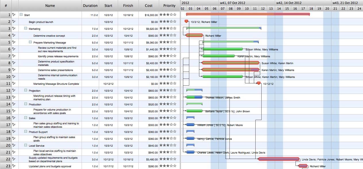
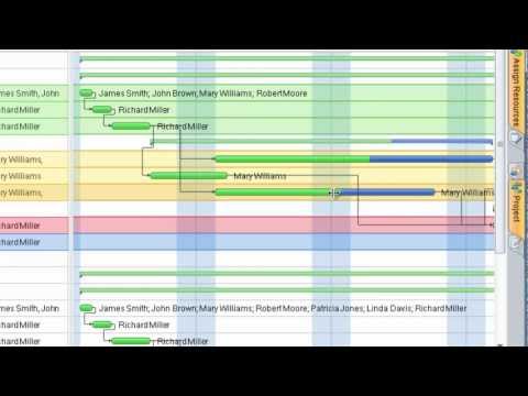
Gant Chart in Project Management
ERD Symbols and Meanings


 Telecommunication Network Diagrams
Telecommunication Network Diagrams solution extends ConceptDraw DIAGRAM software with samples, templates, and great collection of vector stencils to help the specialists in a field of networks and telecommunications, as well as other users to create Computer systems networking and Telecommunication network diagrams for various fields, to organize the work of call centers, to design the GPRS networks and GPS navigational systems, mobile, satellite and hybrid communication networks, to construct the mobile TV networks and wireless broadband networks.
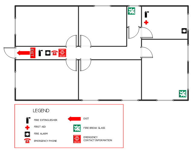
This office fire escape floor plan example shows layout of firefighting equipment and scheme of evacuation ways.
"Fire protection is the study and practice of mitigating the unwanted effects of potentially destructive fires. It involves the study of the behaviour, compartmentalisation, suppression and investigation of fire and its related emergencies, as well as the research and development, production, testing and application of mitigating systems. In structures, be they land-based, offshore or even ships, the owners and operators are responsible to maintain their facilities in accordance with a design-basis that is rooted in laws, including the local building code and fire code, which are enforced by the Authority Having Jurisdiction. Buildings must be constructed in accordance with the version of the building code that is in effect when an application for a building permit is made. Building inspectors check on compliance of a building under construction with the building code. Once construction is complete, a building must be maintained in accordance with the current fire code, which is enforced by the fire prevention officers of a local fire department. In the event of fire emergencies, Firefighters, fire investigators, and other fire prevention personnel called to mitigate, investigate and learn from the damage of a fire. Lessons learned from fires are applied to the authoring of both building codes and fire codes." [Fire protection. Wikipedia]
The example "Office fire and emergency plan" was created using the ConceptDraw PRO diagramming and vector drawing software extended with the Fire and Emergency Plans solution from the Building Plans area of ConceptDraw Solution Park.
Fire escape plan
Building Drawing. Design Element: Piping Plan


What is Gantt Chart (historical reference)

- Example Of Ship Network Layout
- Plant Layout Plans | Aerospace and Transport | Telecommunication ...
- Example Network Layout Of A Ship
- Network Layout Plan Ship
- Ship To Satellite Layout
- Network Layout Of A Ship
- Interior Design Office Layout Plan Design Element | Draw And Label ...
- Warehouse layout floor plan | Warehouse with conveyor system ...
- Plant Layout For Ship Container Company
- Free Visio Ship Stencil
- Ship
- ERD Symbols and Meanings | Plant Layout Plans | Interior Design ...
- Examples of Flowcharts, Org Charts and More | Network Layout ...
- Aerospace and Transport | Plant Layout Plans | Entity-Relationship ...
- Ships Network Layout
- Plant Layout Plans
- Plant Layout Examples
- Plant Layout Plans | How to Create a Plant Layout Design | Plant ...
- Ship Shape Building Drawing