Example of DFD for Online Store (Data Flow Diagram)


ER Diagram for Cloud Computing

DFD Flowchart Symbols

Booch OOD Diagram

UML Deployment Diagram. Design Elements

Jacobson Use Cases Diagram

How to create a UML Diagram

UML Diagram of Parking

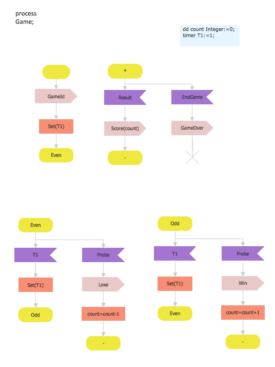
SDL Diagram
How to create your UML Diagram

UML Diagram for Mac

Bubble Chart
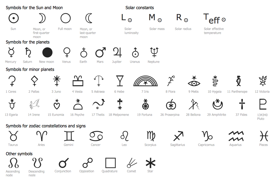
Astronomy Symbols
Introductory Guide to Rapid UML Solution

- Er Diagram For Medical Store Management System
- Erd Of Medical Store
- Er Diagram Of Medical Store Step By Step Showing System
- Er Diagram Of Medicine Store Management System
- 1 Level Dfd And Erd Of Medical Management System Project
- E R Diagram Of Medical Store Automation System
- Er Diagram For Medical Shop
- Erd For Medical Store Management System
- Er Model For Medical Management System
- ER Diagram for Cloud Computing | Example of DFD for Online Store ...
- ER Diagram for Cloud Computing | Example of DFD for Online Store ...
- Erd Of Medical Store With Explanation
- ER Diagram Of Medical Store Database Management System
- ER Diagram for Cloud Computing | Example of DFD for Online Store ...
- Er Diagram For Healthcare Management System
- UML Class Diagram Example - Medical Shop | Entity Relationship ...
- Store Management Er Diagram
- UML Class Diagram Example - Medical Shop | Entity-Relationship ...
- Data Flow Diagram Of Medical Store Management System
- Components of ER Diagram | DFD Flowchart Symbols | Product ...