How To use House Electrical Plan Software


How To use Electrical and Telecom Plan Software


 Electric and Telecom Plans
The Electric and Telecom Plans solution providing the electric and telecom-related stencils, floor plan electrical symbols and pre-made examples is useful for electricians, interior designers, telecommunications managers, builders and other technicians when creating the electric visual plans and telecom drawings, home electrical plan, residential electric plan, telecom wireless plan, electrical floor plans whether as a part of the building plans or the independent ones.
Wiring Diagram Floor Software

Electrical Symbols — Terminals and Connectors

The vector stencils library "Video and audio" contains 50 symbols of devices and equipment.
Use it for drawing audio and video system layouts, cabling floor plans, electrical circuit schematic and wiring diagrams in the ConceptDraw PRO diagramming and vector drawing software.
The vector stencils library "Video and audio" is included in the Electric and Telecom Plans solution from the Building Plans area of ConceptDraw Solution Park.
Audio amplifier

RF amplifier

Video amplifier

Generic automatic switcher

Generic A/V switcher

Generic source component

System components

Headphone jack

Infrared receiver

Infrared transmitter

Music keypad

Mono speaker outlet

Stereo speaker outlet

Speaker ceiling

Speaker in-wall

Speaker subwoofer

Speaker weatherproof

Buzzer and bleeper

Piezo transducer

Microphone

Earphone

Cable antenna outlet

Master antenna outlet

Volume control

Volume control

Flush mounted intercom unit

Master intercom and directory unit

Floor mounted microphone outlet

Wall mounted microphone outlet

Ceiling mounted speaker

Speaker horn

Wall mounted speaker

Call in switch

Ceiling mounted paging speaker

Wall mounted paging speaker

Flush mounted data floor outlet

Flush mounted data floor outlet

Flush mounted data / telephone floor outlet

Surface mounted data floor outlet

Surface mounted data floor outlet

Surface mounted data / telephone floor outlet

Data outlet

Telephone outlet

Telephone, data outlet

Wall mounted telephone outlet

Equipment cabinet

Free standing equipment rack

Plywood backboard

Terminal cabinet with plywood backing

Wall mounted equipment rack

Electrical Design Software

 Electrical Engineering
This solution extends ConceptDraw DIAGRAM.9.5 (or later) with electrical engineering samples, electrical schematic symbols, electrical diagram symbols, templates and libraries of design elements, to help you design electrical schematics, digital and analog
Electrical Symbols — Integrated Circuit

Electrical Symbols — Analog and Digital Logic

CAD Drawing Software for Making Mechanic Diagram and Electrical Diagram Architectural Designs

Audio Visual Connectors Types

Process Flow Diagram Symbols

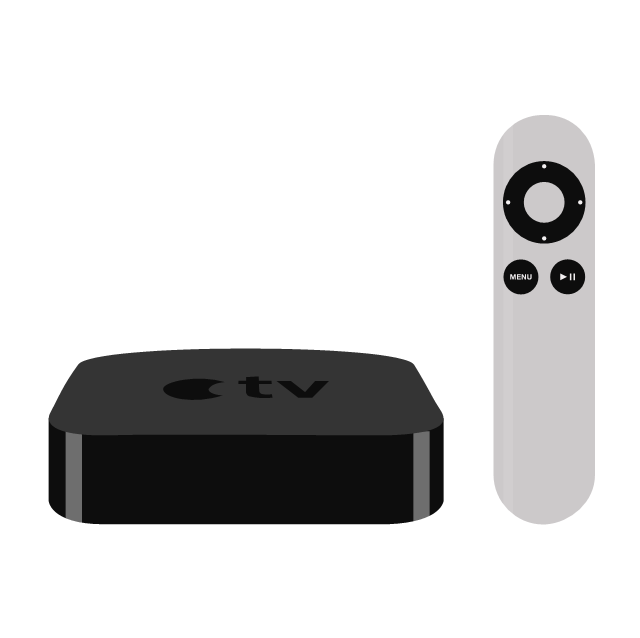
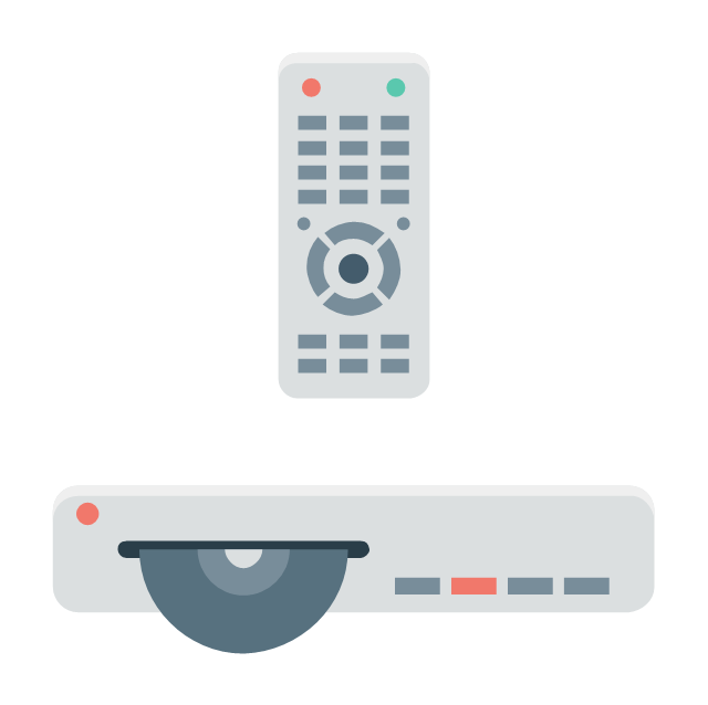
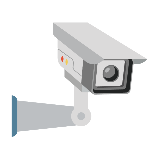
The vector stencils library "TV, Photo and Video" contains 52 television, digital photo and video icons.
Use it to design your audio, video and multimedia illustrations, presentations, web pages and infographics with ConceptDraw PRO diagramming and vector drawing software.
The vector stencils library "TV, Photo and Video" is included in the Audio, Video, Media solution from the Illustration area of ConceptDraw Solution Park.
Television set

TV set

Portable TV set

Apple TV
Wide LCD monitor

Plasma TV

HD screen

Antenna TV

Retro TV

Digital camera

Compact camera 1

Compact camera 2

Photo camera

Camera shutter

Photo images

Photos

Video cassette

Cassette

VHS

Film reel

Video

Movie

Clapboard

Clapper

Video cam

Video camera

Handy cam

Digital camcorder

Movie camera

Video record

Projector

Movie projector 1

Movie projector 2

Video projector 3

Overhead projector

Projector screen

Cinema

DVD video recorder

Video player

DVD player 1
DVD player 2

Remote

Remote control 1
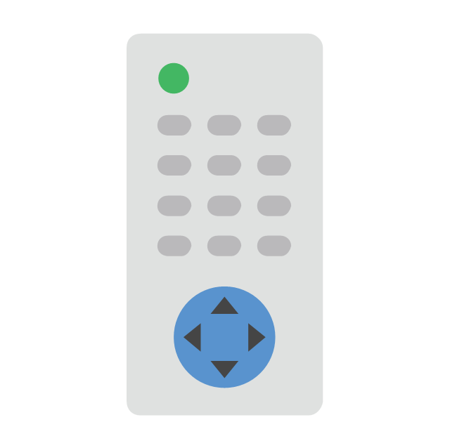
Remote control 2

HDMI video cable

CCTV dome camera

Dome camera

Surveillance camera
CCTV camera 1

CCTV camera 2

Security camera 1

Security camera 2

The vector stencils library "Lighting" contains 55 symbols of lighting devices and equipment.
Use these shapes for drawing lighting design floor plans, circuit schematic and wiring diagrams, cabling layouts, and reflected ceiling plans in the ConceptDraw PRO diagramming and vector drawing software.
The vector stencils library "Lighting" is included in the Electric and Telecom Plans solution from the Building Plans area of ConceptDraw Solution Park.
Luminaire ceiling mount

Enclosed ceiling luminaire

Wall light

Down lighter

Outdoor lightning

Outdoor lightning, bollard

1-light bar

2-light bar

4-light bar

6-light bar

8-light bar

Batten fluorescent, 1 lamp

Batten fluorescent, 2 lamps

Batten fluorescent, 3 lamps

Batten fluorescent, 4 lamps

Surface Fluorescent Light

Modular fluorescent fitting

Modular fluorescent fitting, inverter

Modular fluorescent fitting 2

Emergency light

Emergency light 2

Emergency sign

Emergency Light, Recessed

Light, Surface Mounted

Ceiling Light Outlet

Recessed Ceiling Light

Ceiling Fan

Ceiling Light with Pull Cord

Weatherproof Landscape Light

Wall Light Outlet

Control Keypad

Emergency Battery Unit

Emergency Battery Unit with two Lights

Emergency Single Light, Remote Mounted

Emergency Duplex Light, Remote Mounted

Spotlight, Single Head

Spotlight, Double Head

Exit Sign, Pendant Mounted

Exit Sign, Wall Mounted

Light, Pole Mounted

Light Flood, Pole Mounted

Light Flood, Wall Mounted

Light, Stanchion Mounted

Twin Lights, Pendant Mounted

Inground Light, Floor Mounted

Suspended Light

Suspended Lights

Integrated Light

Lights, Track Mounted

Night Light

Roadway Light, Cobra Head

Louvers

Light, Directional Accent

Light, Directional Aiming Line

Light, Directional Arrow
The vector stencils library "Landmarks" contains 69 landmark symbols of buildings, waterways, scale and directional indicators for labeling transportation and directional maps, road and route maps, street and transit maps, locator and tourist maps.
The pictograms example "Landmarks - Vector stencils library" was created using the ConceptDraw PRO diagramming and vector drawing software extended with the Directional Maps solution from the Maps area of ConceptDraw Solution Park.
The pictograms example "Landmarks - Vector stencils library" was created using the ConceptDraw PRO diagramming and vector drawing software extended with the Directional Maps solution from the Maps area of ConceptDraw Solution Park.
Viewpoint

North arrow
North arrow
Building

Building

Town house

Suburban home

Skyscraper
Town hall

Public house

Petrol station
Gas station
Factory

School

Warehouse
Hospital

Fire station

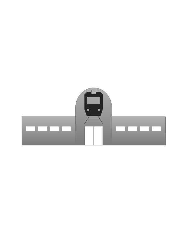
Train station
Condos

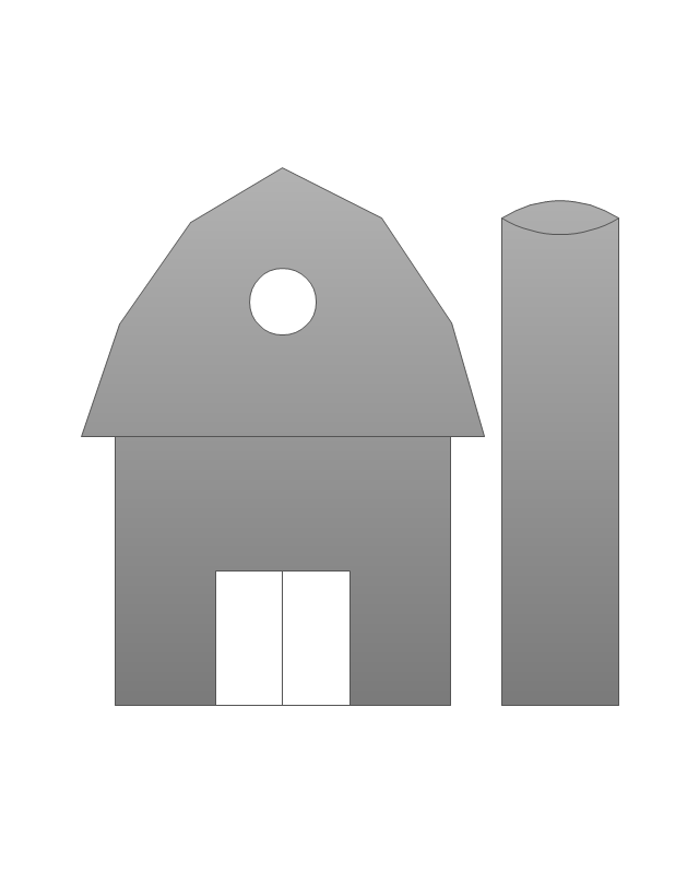
Barn
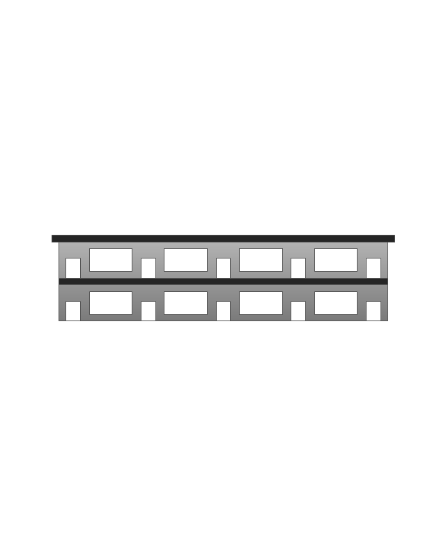
Motel
Convenience store

Shopping centre

City

Church

Cathedral

National tail train station

Train railway

Bus stop

Tramlink

Marina / Ferry dock

Car ferry

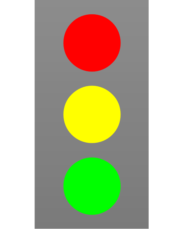
Stop light
Airport

Airport

Underground / Subway / Metro

Taxi

Bicycle parking

Parking

Fuel / Gas / Petrol

Police

Hospital

Wheelchair access

First aid

Telephone

Post office

Landmarks and museums

University

Shopping

Refreshments / Public House

Restrooms / Toilets

Park

Zoo

Information center

Stadium 1
Stadium 2
Park

Tree

Fir-tree

Ocean

Lake

River

Angled river

Forked river

Curved river

Curved river

Flexible river

Bridge

Scale
Vehicular Network

The vector stencils library "Network layout floorplan" contain 34 symbol icons for drawing computer network floor plans, communication equipment layouts, and structured cabling diagrams.
"Structured cabling is building or campus telecommunications cabling infrastructure that consists of a number of standardized smaller elements (hence structured) called subsystems. ...
Structured cabling design and installation is governed by a set of standards that specify wiring data centers, offices, and apartment buildings for data or voice communications using various kinds of cable, most commonly category 5e (CAT-5e), category 6 (CAT-6), and fibre optic cabling and modular connectors. These standards define how to lay the cabling in various topologies in order to meet the needs of the customer, typically using a central patch panel (which is normally 19 inch rack-mounted), from where each modular connection can be used as needed. Each outlet is then patched into a network switch (normally also rack-mounted) for network use or into an IP or PBX (private branch exchange) telephone system patch panel." [Structured cabling. Wikipedia]
The design elements example "Network layout floorplan - Vector stencils library" was created using the ConceptDraw PRO diagramming and vector drawing software extended with the Network Layout Floor Plans solution from the Computer and Networks area of ConceptDraw Solution Park.
PC

Scanner

Switch

Router

Modem

Hub

Rack Mount

Printer

Floor Mounted Outlet

Single Outlet

Duplex Outlet

Direct bus cable

Tops or bottoms bus cable

Side to side bus cable

Multi-tree bus cable

Bottom to side bus cable

Sides bus cable

Door

Door, threshold

Door, stop

Door, stop, threshold

Door, frame

Door, frame, threshold

Door, frame, stop

Door, frame, stop, threshold

Window

Window, sill

Window, sash

Window, sash, sill

Window, frame

Window, frame, sill

Window, frame, sash

Window, frame, sash, sill

- Video Download Of House Wiring
- House Wiring In Hindi Videos Download
- Electrician Wiring Video Download
- How To use House Electrical Plan Software | Electrition Video
- House Wiring Video Download In Bangla
- Wiring Diagrams with ConceptDraw PRO | How To use House ...
- Electric and Telecom Plans | Electrical Diagram Home Wiring Free ...
- Electric and Telecom Plans | Download Electrician Wiring Room Video
- 3gp House Wiring Video Download
- House Application Electrician Video Download
- Electrical House Waring Digarm Video Dawnlod
- House Wire Video Download
- How Do House Wiring Video Download
- Electrical House Wiring In Hindi Daunlod
- Basic Electrical Video Tamil Download
- Home Electric Board Wiring Video Download
- House Wiring Cideo Downlod
- Electrician Wiring Hd Video
- Download Video Of House Wiring
- Electrical Symbols, Electrical Diagram Symbols | Electrical Symbols ...