Electrical Design Software

CAD Drawing Software for Making Mechanic Diagram and Electrical Diagram Architectural Designs


How To use House Electrical Plan Software

How To use Electrical and Telecom Plan Software


Interior Design. Machines and Equipment — Design Elements

Electrical Symbols, Electrical Diagram Symbols

 Electrical Engineering
This solution extends ConceptDraw DIAGRAM.9.5 (or later) with electrical engineering samples, electrical schematic symbols, electrical diagram symbols, templates and libraries of design elements, to help you design electrical schematics, digital and analog
Building Drawing. Design Element: Piping Plan

Electrical Drawing Software and Electrical Symbols

Electrical and Telecom Plan Software

Interior Design. Registers, Drills and Diffusers — Design Elements

Electrical Engineering

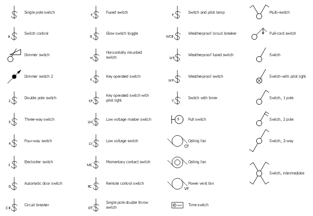
The vector stencil library "RCP-Electrical switches" contains 35 light switch symbols.
Use it to design your reflected ceiling plan with ConceptDraw DIAGRAM software.
"In electrical engineering, a switch is an electrical component that can "make" or "break" an electrical circuit, interrupting the current or diverting it from one conductor to another. The mechanism of a switch removes or restores the conducting path in a circuit when it is operated. It may be operated manually, for example, a light switch or a keyboard button, may be operated by a moving object such as a door, or may be operated by some sensing element for pressure, temperature or flow. A switch will have one or more sets of contacts, which may operate simultaneously, sequentially, or alternately." [Switch. Wikipedia]
"In electrical wiring, a light switch is a switch most commonly used to operate electric lights, permanently connected equipment, or electrical outlets. Portable lamps such as table lamps may have a light switch mounted on the socket, base, or in-line with the cord. Manually operated on/ off switches may be substituted by dimmer switches that allow controlling the brightness of lamps as well as turning them on or off, time-controlled switches, occupancy-sensing switches, and remotely controlled switches and dimmers." [Light switch. Wikipedia]
The light switch symbols example "Design Elements - RCP-Electrical switches" is included in Reflected Ceiling Plans solution from the Building Plans area of ConceptDraw Solution Park.
Vector stencils
The vector stencils library "Electrical circuits" contains 49 element symbols of electrical and electronic devices, including ignitors, starters, transmitters, circuit protectors, transducers, radio and audio equipment.
Use it for drawing electronic circuit diagrams and electrical schematics.
"An electrical network is an interconnection of electrical elements such as resistors, inductors, capacitors, voltage sources, current sources and switches. An electrical circuit is a network consisting of a closed loop, giving a return path for the current. Linear electrical networks, a special type consisting only of sources (voltage or current), linear lumped elements (resistors, capacitors, inductors), and linear distributed elements (transmission lines), have the property that signals are linearly superimposable. They are thus more easily analyzed, using powerful frequency domain methods such as Laplace transforms, to determine DC response, AC response, and transient response.
A resistive circuit is a circuit containing only resistors and ideal current and voltage sources. Analysis of resistive circuits is less complicated than analysis of circuits containing capacitors and inductors. If the sources are constant (DC) sources, the result is a DC circuit.
A network that contains active electronic components is known as an electronic circuit. Such networks are generally nonlinear and require more complex design and analysis tools." [Electrical network. Wikipedia]
The symbils example "Design elements - Electrical circuits" was drawn using the ConceptDraw PRO diagramming and vector drawing software extended with the Electrical Engineering solution from the Engineering area of ConceptDraw Solution Park.
Electrical circuit elements

Home Electrical Plan

Electrical Schematics

Wiring Diagrams with ConceptDraw DIAGRAM

The vector stencil library "RCP-Electrical" contains 23 electrical component symbols.
Use it to design your reflected ceiling plan with ConceptDraw DIAGRAM software.
"An electronic symbol is a pictogram used to represent various electrical and electronic devices or functions, such as wires, batteries, resistors, and transistors, in a schematic diagram of an electrical or electronic circuit." [Electronic symbol. Wikipedia]
"An electronic component is any basic discrete device or physical entity in an electronic system used to affect electrons or their associated fields. Electronic components are mostly industrial products, available in a singular form..." [Electronic component. Wikipedia]
The electrical component symbols example "Design Elements - RCP-Electrical" is included in Reflected Ceiling Plans solution from the Building Plans area of ConceptDraw Solution Park.
Vector stencils
The vector stencils library "Qualifying" contains 56 qualifying symbols of radiation, polarity, phase, windings, wire, ground, connection, connector, coaxial, electret.
Use these signs to annotate or specify characteristics of objects in electrical drawings, electronic schematics, circuit diagrams, electromechanical drawings, and wiring diagrams, cabling layout diagrams.
"An electrical drawing, is a type of technical drawing that shows information about power, lighting, and communication for an engineering or architectural project. Any electrical working drawing consists of "lines, symbols, dimensions, and notations to accurately convey an engineering's design to the workers, who install the electrical system on the job".
A complete set of working drawings for the average electrical system in large projects usually consists of:
(1) A plot plan showing the building's location and outside electrical wiring.
(2) Floor plans showing the location of electrical systems on every floor.
(3) Power-riser diagrams showing panel boards.
(4) Control wiring diagrams.
(5) Schedules and other information in combination with construction drawings.
Electrical drafters prepare wiring and layout diagrams used by workers who erect, install, and repair electrical equipment and wiring in communication centers, power plants, electrical distribution systems, and buildings." [Electrical drawing. Wikipedia]
The signs example "Design elements - Qualifying" was drawn using the ConceptDraw PRO diagramming and vector drawing software extended with the Electrical Engineering solution from the Engineering area of ConceptDraw Solution Park.
Qualifying symbols

The vector stencils library "Electrical and telecom" contains 83 symbols of electrical and telecommunication equipment for electrical drawings and wiring diagrams of buildings, communication centers, power plants and electrical distribution systems.
"An electrical drawing, is a type of technical drawing that shows information about power, lighting, and communication for an engineering or architectural project." [Electrical drawing. Wikipedia]
Use the design elements library "Electrical and telecom" to design your own electrical drawings, plot plans of the building outside electrical wiring, floor plans with electrical and telecommunication systems layout, power-riser diagrams with panel boards, control wiring diagrams and cabling layout schemes, reflected ceiling plans and lighting panels layouts using the ConceptDraw PRO diagramming and vector drawing software.
The shapes library "Electrical and telecom" is included in the Electric and Telecom Plans solution from the Building Plans area of ConceptDraw Solution Park.
Electrical and telecom symbols

- House Electrical Design And Drafting Pdf
- Interior Design . Sport Fields — Design Elements | Sport Field Plans ...
- Gym Electrical Design
- Office Layout Plans | Lighting and switch layout | Design Elements ...
- Cafe electrical floor plan | Restaurant Floor Plan | How To Create ...
- Design elements - Electrical circuits | How To use House Electrical ...
- Hotel Electrical Design Pdf
- How To use House Electrical Plan Software | Electrical Design ...
- Cafe electrical floor plan | Design elements - Qualifying | Network ...
- Building Drawing. Design Element: Piping Plan | Electrical Design ...
- Design elements - Walls, shell and structure | Electrical and telecom ...
- Switches - Vector stencils library | Electrical and telecom - Vector ...
- Electrical Symbols, Electrical Diagram Symbols | Electrical and ...
- Lighting - Vector stencils library | Design elements - Lighting ...
- Pdf Electrical Engineering Drawing And Design 1
- Electric and Telecom Plans | Electrical Design For A Two Bedroom ...
- Electrical Design For Basketball Court
- Plumbing and Piping Plans | Electrical Design For 3bedroom Flat
- Three Bedroom Bungalow Electrical Design
- How To use House Electrical Plan Software | Electrical Design ...