Electrical Symbols — Thermo

How To use House Electrical Plan Software


Electrical Symbols — MOSFET

Mechanical Drawing Symbols

Electrical Symbols — Transistors

 Electrical Engineering
This solution extends ConceptDraw DIAGRAM.9.5 (or later) with electrical engineering samples, electrical schematic symbols, electrical diagram symbols, templates and libraries of design elements, to help you design electrical schematics, digital and analog
Electrical Symbols, Electrical Schematic Symbols

Electrical Symbols — Rotating Equipment

Electrical Symbols — Lamps, Acoustics, Readouts

Electrical Symbols, Electrical Diagram Symbols

 Composition Dashboard
Composition dashboard solution extends ConceptDraw DIAGRAM software with templates, samples and vector stencils library with charts and indicators for drawing visual dashboards showing data composition.
This HVAC schematics sample depicts the house cool mode of central air pool heater. It was drawn on the base of the HVAC schematics in the post "Central Air Pool Heater" from the Nathan Stratton's blog.
"With House Cool Mode, hot gas leaves the compressor runs through the reversing value into the condenser where it condenses into a liquid. Valve #1 is ON so liquid is able to leave the outside unit and run through the filter dryer and site glass into the evaporator upstairs in the house where the liquid flashes into a gas as it passes through the expansion valve and absorbs heat from the air passing through the evaporator. The cold gas travels downstairs and outside to the compressor and the cycle starts all over again." [robotics.net/ projects/ central-air-pool-heater/ ]
The HVAC schematics example "Central air pool heater" was created using the ConceptDraw DIAGRAM diagramming and vector drawing software extended with the HVAC Plans solution from the Building Plans area of ConceptDraw Solution Park.
HVAC schematics

 Pie Charts
Pie Charts are extensively used in statistics and business for explaining data and work results, in mass media for comparison (i.e. to visualize the percentage for the parts of one total), and in many other fields. The Pie Charts solution for ConceptDraw DIAGRAM offers powerful drawing tools, varied templates, samples, and a library of vector stencils for simple construction and design of Pie Charts, Donut Chart, and Pie Graph Worksheets.
The vector stencils library "Laboratory equipment" contains 31 clipart icons of chemical laboratory equipment and labware.
Use these shapes for drawing part assembly and mounting schemes of glassware apparatus in chemical experiment diagrams and illustrations in the ConceptDraw PRO diagramming and vector drawing software extended with the Chemistry solution from the Science and Education area of ConceptDraw Solution Park.
Use these shapes for drawing part assembly and mounting schemes of glassware apparatus in chemical experiment diagrams and illustrations in the ConceptDraw PRO diagramming and vector drawing software extended with the Chemistry solution from the Science and Education area of ConceptDraw Solution Park.
Vigreux distillation column

Hirsch funnel

Oil bath

Steam bath

Thermometer

Tap (valve)
--laboratory-equipment---vector-stencils-library.png--diagram-flowchart-example.png)
Vacuum adaptor

Liebig condenser (long)
-laboratory-equipment---vector-stencils-library.png--diagram-flowchart-example.png)
Liebig condenser (short)
-laboratory-equipment---vector-stencils-library.png--diagram-flowchart-example.png)
Water faucet

Büchner flask

Stemless funnel

Stemmed funnel

Separatory funnel

Heating mantle

Hot plate

Gas tap

Folded filter paper

Y-Adaptor

Claisen adapter

Bunsen burner

Büchner funnel

Erlenmeyer flask, 25ml

Round-bottom flask, 50ml

Round-bottom flask, 250ml

Beaker 100ml, filled

Beaker 100ml, empty

Beaker 500ml, filled

Beaker 500ml, empty

Erlenmeyer flask 250ml, filled

Erlenmeyer flask 250ml, empty

 Mechanical Engineering
This solution extends ConceptDraw DIAGRAM.9 mechanical drawing software (or later) with samples of mechanical drawing symbols, templates and libraries of design elements, for help when drafting mechanical engineering drawings, or parts, assembly, pneumatic,
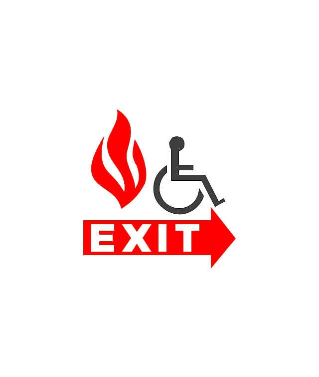
The vector stencils library "Fire and emergency planning" contains 52 symbols of firefighting equipment.
Use these shapes for drawing fire and emergency floor plans, equipment layouts, and evacuation schemes in the ConceptDraw PRO diagramming and vector drawing software extended with the Fire and Emergency Plans solution from the Building Plans area of ConceptDraw Solution Park.
www.conceptdraw.com/ solution-park/ building-fire-emergency-plans
Direction Arrow
Double Stairs
Stairs
Elevator

Emergency Exit

Handicapped Emergency Exit
Emergency Phone 1

Use Stairs in Fire

Fire Escape or Fire Exit

Black Fire Alarm

Red Fire Alarm

Fire Extinguisher 1
Fire Hose without text
Fire Extinguisher 2
Fire Hose with black text
Fire Hose with red text
First Aid

Left Arrow
Right Arrow
You are here

Biohazard

Radiation Hazard
Obstructions

Hazardous Materials Storage
Sprinkler Connections

Private Fire Detection System

Exits and Entrances

Water Supplies

Elevator Shaft

Nearest Fire Hydrant

Electric Shut Off
Knox Box Location

Water Shut Off
Other Vertical Openings

Roof Access

Gas Shut Off

Emergency Phone 2

Emergency contact information
Fire Alarm
Fire Break Glass

Fire Escape

Danger Compressed Gas
Flammable Material
Oxidant Material
Harmful Chemicals

Non Ionising Radiation
Corrosive Material
High Voltage

Dangerous Chemical

Danger of Death

Fire Point

Fire Blanket

Interior Design. Piping Plan — Design Elements

Electrical Diagram Software

- Process Flow Diagram Symbols | Design elements - Heating ...
- Watercraft - Vector stencils library | Resources and energy - Vector ...
- Process Flow Diagram Symbols | Electrical Symbols — Analog and ...
- Design elements - Transistors | Design elements - Electron tubes ...
- Electrical Symbols — Thermo | Electrical Symbols — Resistors ...
- Electrical Symbols, Electrical Diagram Symbols | HVAC control ...
- Electrical Symbols — Switches and Relays | Cisco Switches and ...
- Design elements - Thermo | Instruments - Vector stencils library ...
- P Id Symbols Ppt
- Pump Symbol P Id
- Stations - Vector stencils library | American football positions - Vector ...
- Design elements - Semiconductor diodes | Electrical Symbols ...
- Electrical Symbols — Power Sources | Electrical Symbols — Thermo ...
- P Id Symbols Pdf Download
- Electrical Symbols, Electrical Diagram Symbols | Entity Relationship ...
- Electrical Symbol Of Condenser
- Electrical Symbols — Thermo | Electrical Symbols — Power Sources ...
- Building Drawing Software for Designing Plumbing | Residential ...
- Electrical Symbols, Electrical Diagram Symbols | How To use House ...
- Design elements - Pumps | Pumps - Vector stencils library ...