UML Collaboration Diagram. Design Elements

Banking System

UML Collaboration Diagram Example Illustration

Bank UML Diagram

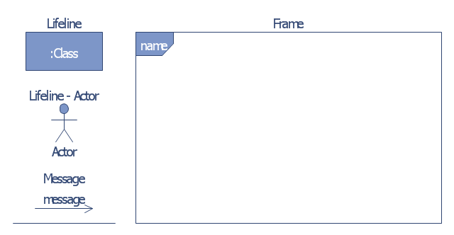
The vector stencils library "Bank UML communication diagram" contains 4 shapes for drawing UML communication (collaboration) diagrams.
Use it for object-oriented modeling of your bank information system.
"A communication diagram in the Unified Modeling Language (UML) 2.0, is a simplified version of the UML 1.x collaboration diagram.
A Communication diagram models the interactions between objects or parts in terms of sequenced messages. Communication diagrams represent a combination of information taken from Class, Sequence, and Use Case Diagrams describing both the static structure and dynamic behavior of a system.
However, communication diagrams use the free-form arrangement of objects and links as used in Object diagrams. In order to maintain the ordering of messages in such a free-form diagram, messages are labeled with a chronological number and placed near the link the message is sent over. Reading a communication diagram involves starting at message 1.0, and following the messages from object to object." [Communication diagram. Wikipedia]
This example of UML communication diagram symbols for the ConceptDraw PRO diagramming and vector drawing software is included in the ATM UML Diagrams solution from the Software Development area of ConceptDraw Solution Park.
UML communication diagram symbols
UML Deployment Diagram Example - ATM System UML diagrams

UML Component for Bank

Introductory Guide to Rapid UML Solution

Systems Engineering

UML Diagram

UML Sequence Diagram Example. SVG Vectored UML Diagrams Tools

UML Class Diagram


UML for Bank

Diagramming Software for Design UML Component Diagrams

Software Diagram Examples and Templates

UML Use Case Diagram Example. Services UML Diagram. ATM system

Create UML Diagram

UML Process Diagram Example

UML Use Case Diagram Example. Registration System

 Rapid UML
Rapid UML solution extends ConceptDraw DIAGRAM software with templates, samples and libraries of vector stencils for quick drawing the UML diagrams using Rapid Draw technology.
- UML Deployment Diagram Example - ATM System UML diagrams ...
- UML use case diagram - Banking system | How to Create a Bank ...
- UML Deployment Diagram Example - ATM System UML diagrams ...
- Bank ATM use case diagram | UML Collaboration Diagram . Design ...
- UML Diagram | Communication Diagram UML2.0 / Collaboration ...
- Diagramming Software for Design UML Collaboration Diagrams ...
- Uml Communication Diagram
- Collaboration Diagram For Online Banking System
- UML Deployment Diagram Example - ATM System UML diagrams ...
- UML Collaboration Diagram (UML2.0) | UML Class Diagram ...
- UML Collaboration Diagram . Design Elements | UML Collaboration ...
- Draw An ER Diagram For Online Banking System
- Collaboration Uml Diagram For Online Shopping System
- UML Deployment Diagram Example - ATM System UML diagrams ...
- Bank UML Diagram | How to Create a Bank ATM Use Case Diagram ...
- Bank UML Diagram | Communication Diagram UML2.0 ...
- Communication Diagram UML2.0 / Collaboration UML1.x ...
- UML Collaboration Diagram (UML2.0) | Design elements - Bank ...
- UML Collaboration Diagram Example Illustration | UML Class ...