UML Class Diagram Example - Medical Shop

UML Class Diagram Tutorial

DFD Flowchart Symbols

UML Collaboration Diagram (UML2.0)


UML Class Diagram. Design Elements

Design Pictorial Infographics. Design Infographics

Entity Relationship Diagram - ERD - Software for Design Crows Foot ER Diagrams
_Win_Mac.png)

Example of DFD for Online Store (Data Flow Diagram)


UML Diagram Types List

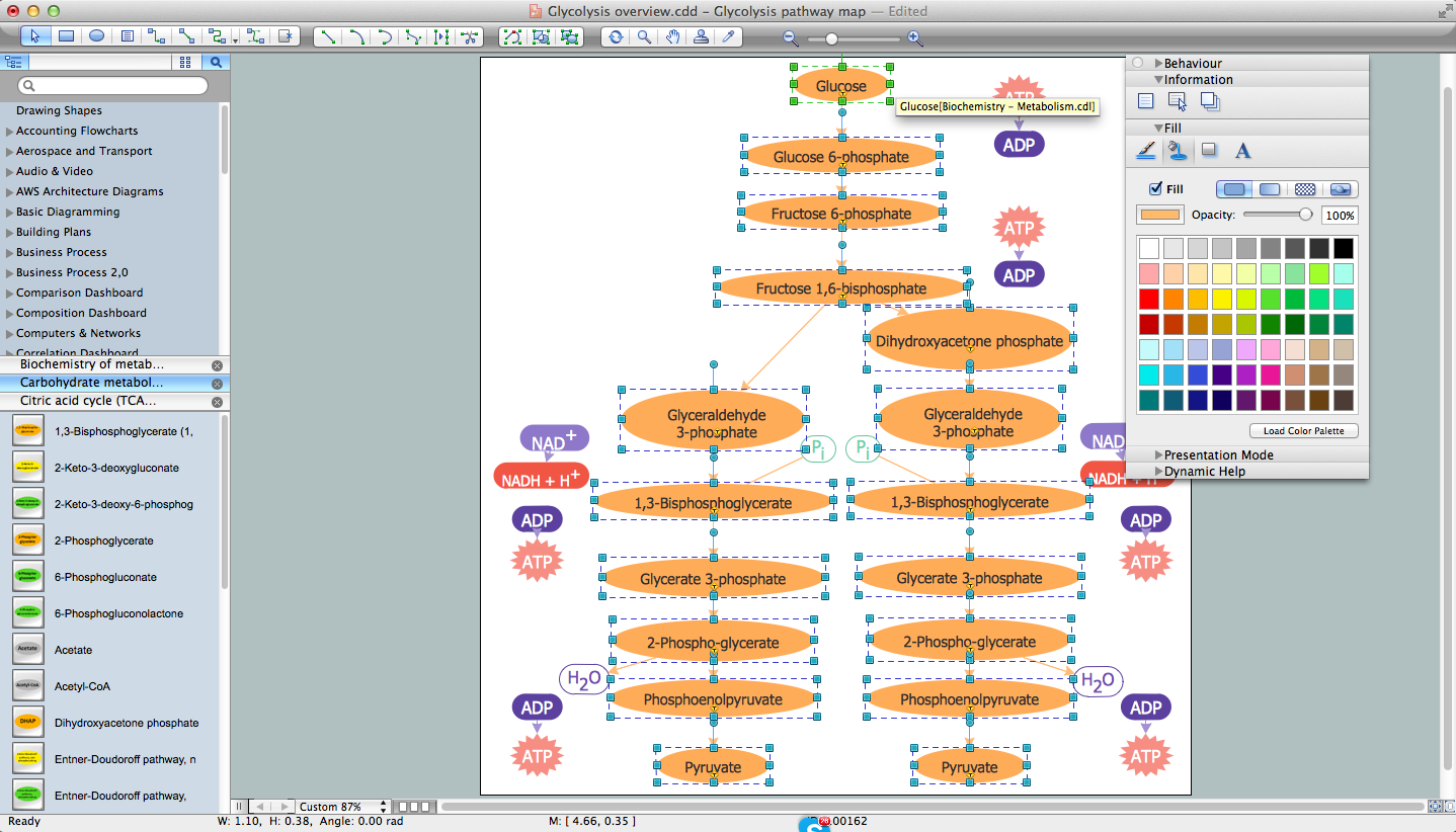
Biology Drawing Software
How to create a UML Diagram

UML Notation

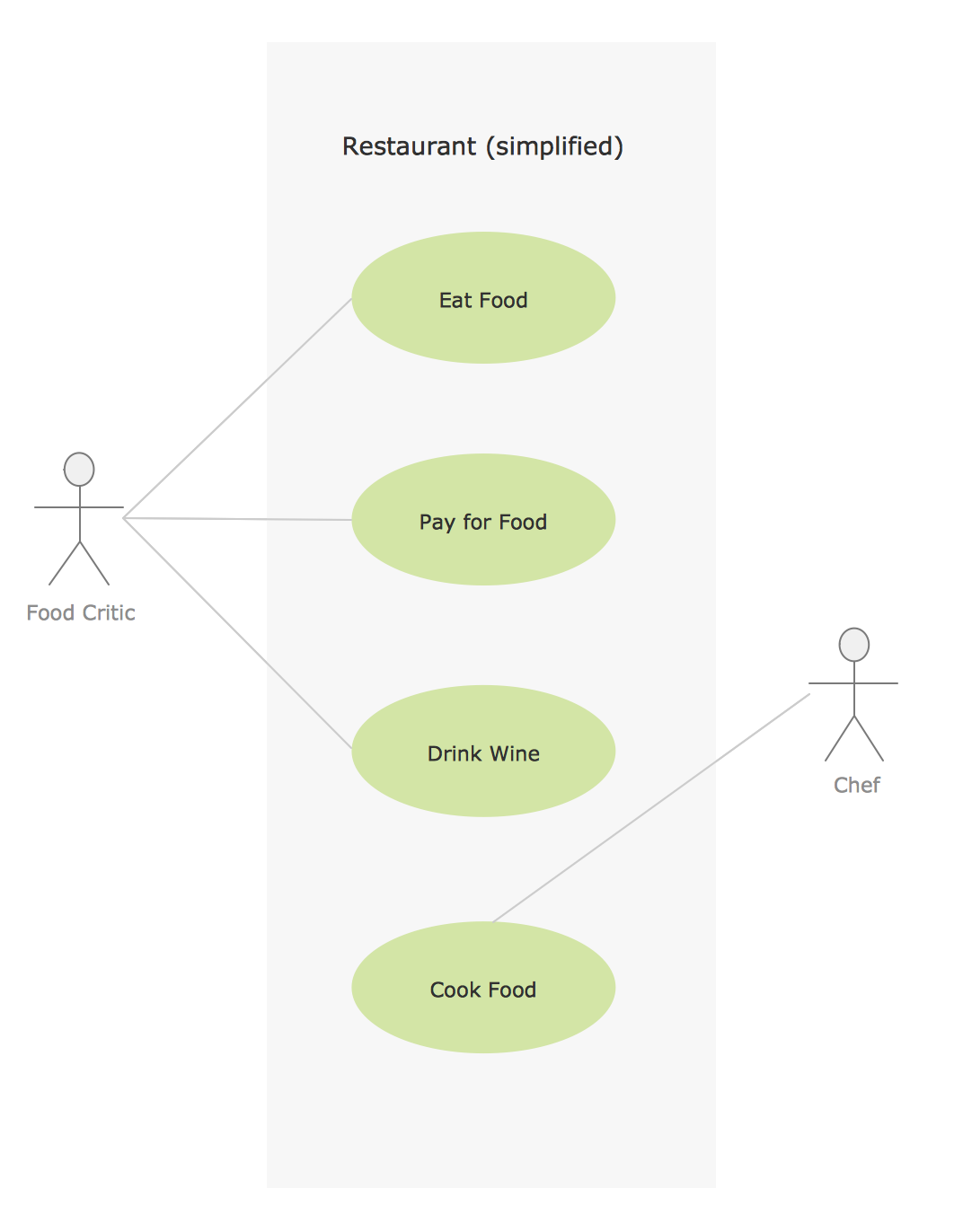
Sample for UML
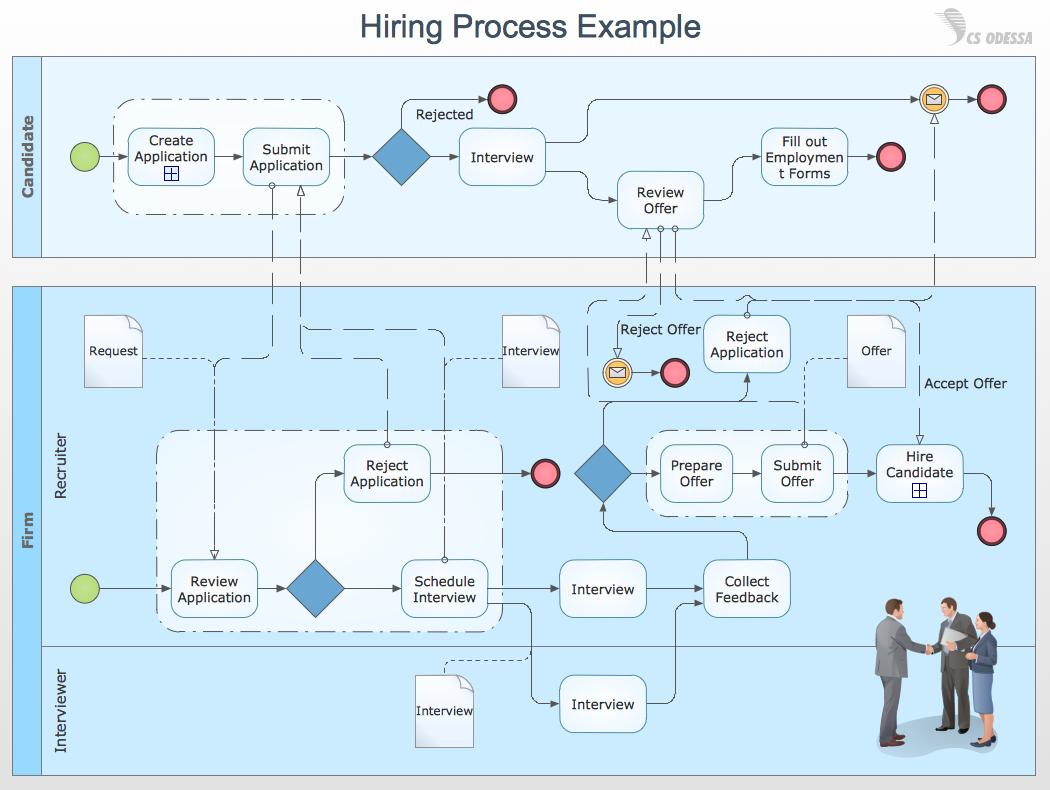
Business Process Modeling with ConceptDraw
- Activity Diagram Of Medical Shop System
- UML Class Diagram Example - Medical Shop | Network Diagrams ...
- Activity Diagram For Medical Shop Management System
- UML Class Diagram Example - Medical Shop | Process Flowchart ...
- UML Class Diagram Example - Medical Shop | Network Diagrams ...
- Activity Diagram For Medical Store Management System
- Activity Diagram Of Medical Shop
- Medical Shop Management System Uml Diagrams
- Activity Diagram For Medical Shop Managemt
- UML Class Diagram Example - Medical Shop | UML Collaboration ...
- Medical Store Management Class Diagram
- Uml Diagrams For Medical Store Management System
- UML Collaboration Diagram (UML2.0) | UML Class Diagram ...
- UML Class Diagram Example - Medical Shop | UML Diagram for ...
- Activity Diagram For Medical Shop Management
- UML Class Diagram Example - Medical Shop | Class Diagram Tool ...
- Download Sequence Diagram Of Medical Stores Management System
- Timing diagram | UML Class Diagram Example - Medical Shop ...
- Activity Diagram For Medical Management
- UML Class Diagram Example - Medical Shop | Enterprise ...