Data Flow Diagram Examples

 Data Flow Diagrams (DFD)
Data Flow Diagrams solution extends ConceptDraw DIAGRAM software with templates, samples and libraries of vector stencils for drawing the data flow diagrams (DFD).
 Sales Flowcharts
The Sales Flowcharts solution lets you create and display sales process maps, sales process workflows, sales steps, the sales process, and anything else involving sales process management.
Gane Sarson Diagram

Sales Process Management

It is effective to use professional software for the sales process management. ConceptDraw DIAGRAM diagramming and vector drawing software extended with Sales Flowcharts solution from the Marketing area of ConceptDraw Solution Park is the best choice.
Organizational Charts with ConceptDraw DIAGRAM

Copying Service Process Flowchart. Flowchart Examples

Map of Germany

 Flowcharts
The Flowcharts solution for ConceptDraw DIAGRAM is a comprehensive set of examples and samples in several varied color themes for professionals that need to represent graphically a process. Solution value is added by the basic flow chart template and shapes' libraries of flowchart notation. ConceptDraw DIAGRAM flow chart creator lets one depict the processes of any complexity and length, as well as design the Flowchart either vertically or horizontally.
 Business Process Diagrams
Business Process Flow Diagrams solution extends the ConceptDraw DIAGRAM BPM software with RapidDraw interface, templates, business process diagrams examples and numerous libraries based on the BPMN 1.2 and BPMN 2.0 standards, which give you the possibility to visualize equally easy simple and complex processes, to design business models, to quickly develop and document in details any business processes on the stages of project’s planning and implementation.
Types of Flowchart - Overview


Work Order Process Flowchart. Business Process Mapping Examples

 Floor Plans
Construction, repair and remodeling of the home, flat, office, or any other building or premise begins with the development of detailed building plan and floor plans. Correct and quick visualization of the building ideas is important for further construction of any building.
Export from ConceptDraw MINDMAP to PowerPoint® Presentation

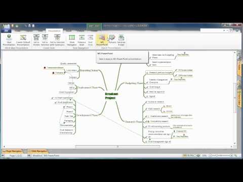
to MS PowerPoint
How to Create Cisco Network Diagram

Software Diagram Examples and Templates

Selecting & Creating Flowcharts

How To Create a Bubble Chart

This example of a Top Level Context Diagram for an information system management process was redesigned from the Wikipedia file: IDEF Top-Level Context Diagram.jpg. [en.wikipedia.org/ wiki/ File:IDEF_ Top-Level_ Context_ Diagram.jpg]
"Graphical notation.
IDEF0 is a model that consists of a hierarchical series of diagrams, text, and glossary cross referenced to each other. The two primary modeling components are:
(1) functions (represented on a diagram by boxes), and
(2) data and objects that interrelate those functions (represented by arrows).
... the position at which the arrow attaches to a box conveys the specific role of the interface. The controls enter the top of the box. The inputs, the data or objects acted upon by the operation, enter the box from the left. The outputs of the operation leave the right-hand side of the box. Mechanism arrows that provide supporting means for performing the function join (point up to) the bottom of the box.
The IDEF0 process.
The IDEF0 process starts with the identification of the prime function to be decomposed. This function is identified on a “Top Level Context Diagram,” that defines the scope of the particular IDEF0 analysis. ... From this diagram lower-level diagrams are generated." [IDEF0. Wikipedia]
The IDEF0 diagram example "Top-level context diagram" was created using the ConceptDraw PRO diagramming and vector drawing software extended with the IDEF0 Diagrams solution from the Software Development area of ConceptDraw Solution Park.
IDEF0 diagram

 Workflow Diagrams
Workflow Diagrams solution extends ConceptDraw DIAGRAM software with samples, templates and vector stencils library for drawing the work process flowcharts.
- Data Flow Diagram (DFD) | DFD Library — Design elements | Data ...
- Data Flow Diagrams (DFD) | Context Level Dfd For Hotel Booking
- Dfd Diagram In Hotel Management Of Website
- Data Flow Diagram For Hotel Management System Level 0
- Dfd Hotel Reservation System
- Data Flow Diagram In Hotel Management
- Data Flow Diagrams (DFD) | Structured Systems Analysis and ...
- Context Level Erd Diagram Of Hotel Management System
- Last resort hotel book room process - DFD | Level 1 Dfd Resort ...
- Process Flowchart | Level 0 Dfd For Bus Reservation System
- Context Level Data Flow Diagram Of Hotel Managment System
- Draw Dfd For Bus Reservation System
- Level 0 Dfd For Hotel Management System
- Example of DFD for Online Store ( Data Flow Diagram ) | Data Flow ...
- Dfd Of Hotel Management System Level 1
- 0level Dfd Of Hotel Management Syste
- Flowchart For Hotel Booking And Reservation Pdf
- External Entity For Hotel System Dfd
- Dfd Level 0 Diagram For Bus Reservation System