Electrical Symbols — Semiconductor Diodes

Electrical Symbols, Electrical Diagram Symbols

Electrical Drawing Software and Electrical Symbols

The vector stencils library "Semiconductor diodes" contains 24 symbols of semiconductor diodes for drawing electronic schematics and circuit diagrams.
"In electronics, a diode is a two-terminal electronic component with asymmetric conductance; it has low (ideally zero) resistance to current in one direction, and high (ideally infinite) resistance in the other. A semiconductor diode, the most common type today, is a crystalline piece of semiconductor material with a p–n junction connected to two electrical terminals. A vacuum tube diode has two electrodes, a plate (anode) and a heated cathode. Semiconductor diodes were the first semiconductor electronic devices. ...
Today, most diodes are made of silicon, but other semiconductors such as selenium or germanium are sometimes used." [Diode. Wikipedia]
The shapes example "Design elements - Semiconductor diodes" was drawn using the ConceptDraw PRO diagramming and vector drawing software extended with the Electrical Engineering solution from the Engineering area of ConceptDraw Solution Park.
Semiconductor diode symbols

Electrical Symbols, Electrical Schematic Symbols

The vector stencils library "Semiconductor diodes" contains 24 symbols of semiconductor diodes.
Use these shapes for drawing electronic schematics and circuit diagrams in the ConceptDraw PRO diagramming and vector drawing software extended with the Electrical Engineering solution from the Engineering area of ConceptDraw Solution Park.
www.conceptdraw.com/ solution-park/ engineering-electrical
Use these shapes for drawing electronic schematics and circuit diagrams in the ConceptDraw PRO diagramming and vector drawing software extended with the Electrical Engineering solution from the Engineering area of ConceptDraw Solution Park.
www.conceptdraw.com/ solution-park/ engineering-electrical
Diode, env
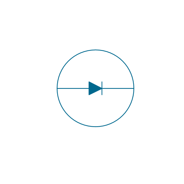
Diode

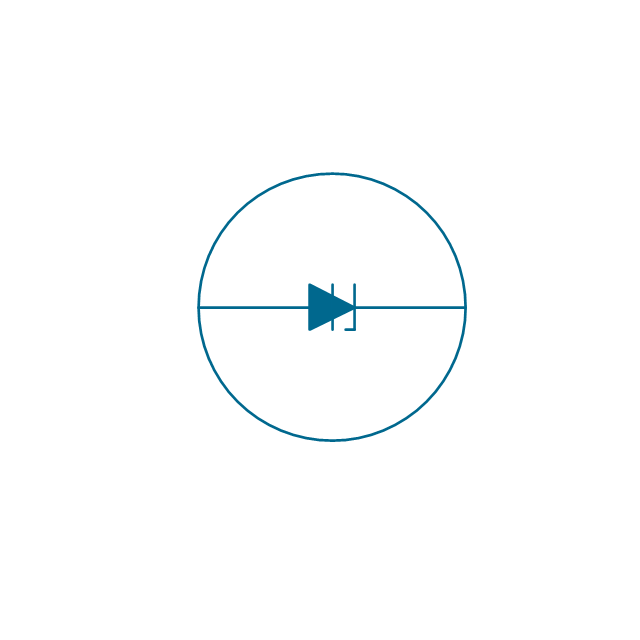
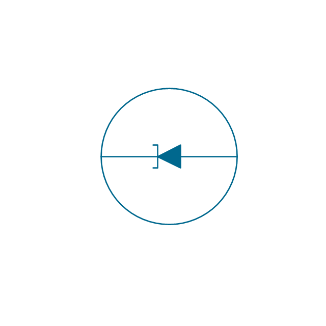
Diode, reverse blocking, env

Diode, reverse blocking

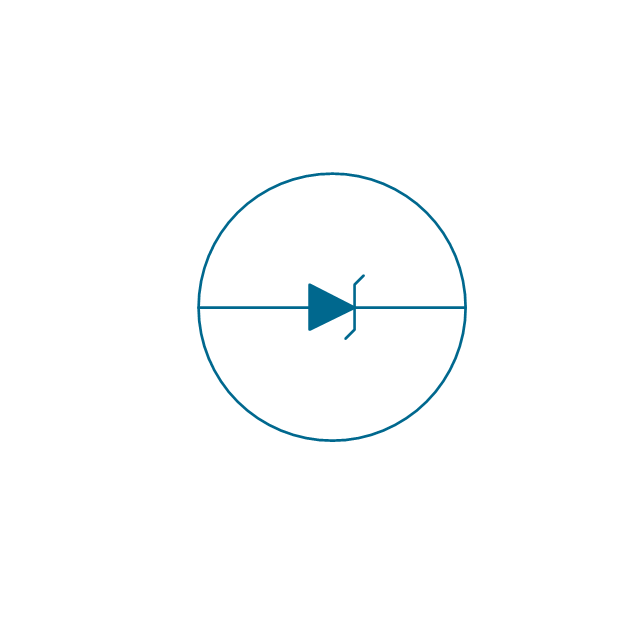
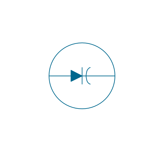
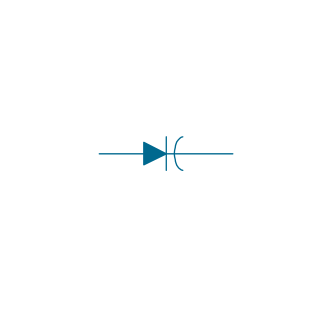
Diode, reverse conducting, env
Diode, reverse conducting

Tunnel diode, env

Tunnel diode

Zener diode, env
Zener diode

Backward diode, env
Backward diode

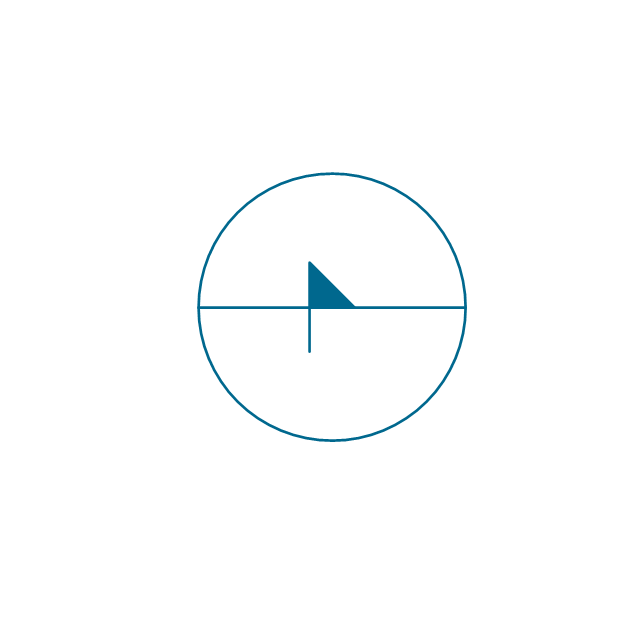
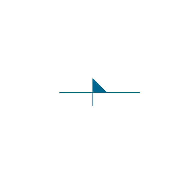
Varactor, env
Varactor
Four layer diode, env
Four layer diode
LED, env
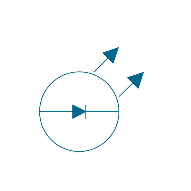
LED
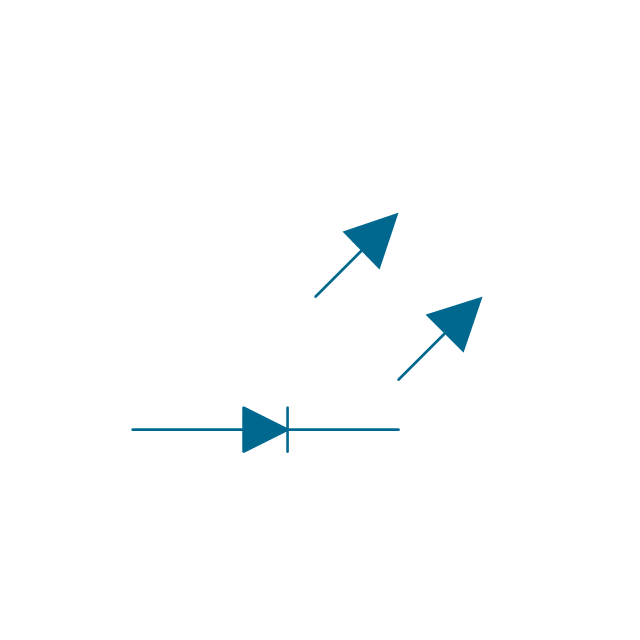
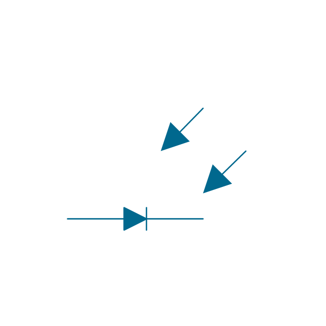
Photo-diode, env
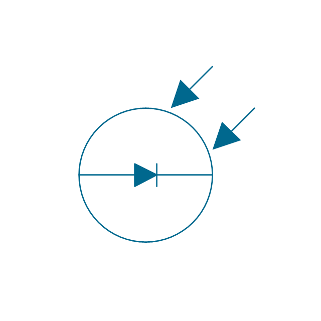
Photo-diode
Breakdown diode, uni-directional, env
Breakdown diode, uni-directional

Breakdown diode, bi-directional, env

Breakdown diode, bi-directional

Electrical Symbols — Semiconductor

Electrical Diagram

Electrical Symbols — Delay Elements

Circuits and Logic Diagram Software

Electrical Symbols — Rotating Equipment

Electrical Symbols — Integrated Circuit

Wiring Diagrams with ConceptDraw DIAGRAM

Electrical Symbols — Qualifying

Electrical Symbols — Electrical Circuits

- Schematic Symbol Zener Diode
- Electrical Symbols — Semiconductor Diodes | Design elements ...
- Electrical Symbols , Electrical Diagram Symbols | Electrical Drawing ...
- Electrical Symbols — Semiconductor Diodes | Semiconductor ...
- Schematic Symbol Of Rectifier Diode
- Electrical Symbols — Semiconductor Diodes | Semiconductor ...
- Electrical Symbols — Semiconductor | Electrical Symbols ...
- Symbol For Semiconductor Diode
- Design elements - Semiconductor diodes | Electrical Symbols ...
- Electrical Symbols , Electrical Diagram Symbols | Electrical Drawing ...
- Electrical Symbols , Electrical Diagram Symbols | Electrical Symbols ...
- Electronic Types Of Diode Symbols Photos In
- Circuit Symbol Draw Of Tetrode
- Electrical Symbols — Semiconductor | Electrical Symbols , Electrical ...
- Electrical Symbols , Electrical Schematic Symbols | Electrical ...
- Electrical Symbols , Electrical Diagram Symbols | Design elements ...
- Mechanical Drawing Symbols | Electrical Symbols — Semiconductor ...
- Diode Vacuum Tube
- Electrical Symbols — Semiconductor Diodes | Electrical Symbols ...
- Circuit Diagram Using Power Semiconductor Diode