Structured Systems Analysis and Design Method (SSADM) with ConceptDraw DIAGRAM

Booch OOD Diagram

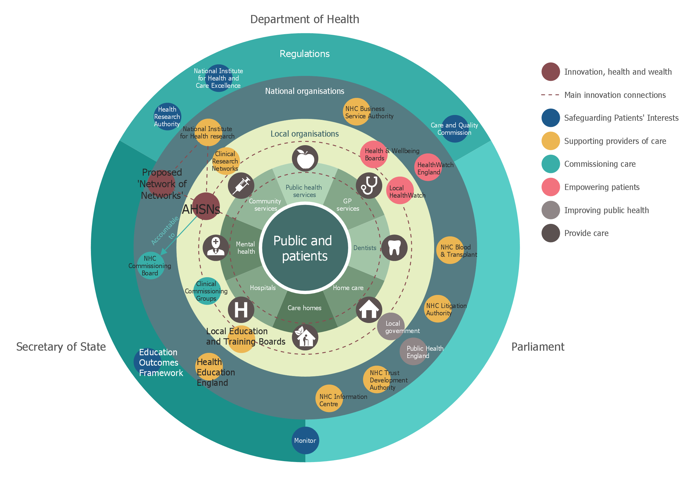
Stakeholder Onion Diagrams
Local area network (LAN). Computer and Network Examples
 diagram")

Examples of Flowcharts, Org Charts and More


Entity Relationship Diagram Examples


UML Business Process

 Business Process Diagrams
Business Process Diagrams solution extends the ConceptDraw DIAGRAM BPM software with RapidDraw interface, templates, samples and numerous libraries based on the BPMN 1.2 and BPMN 2.0 standards, which give you the possibility to visualize equally easy simple and complex processes, to design business models, to quickly develop and document in details any business processes on the stages of project’s planning and implementation.
Sales Process Flowchart Symbols

Competitor Analysis

 Network Layout Floor Plans
Network Layout Floor Plans solution extends ConceptDraw DIAGRAM software functionality with powerful tools for quick and efficient documentation the network equipment and displaying its location on the professionally designed Network Layout Floor Plans. Never before creation of Network Layout Floor Plans, Network Communication Plans, Network Topologies Plans and Network Topology Maps was not so easy, convenient and fast as with predesigned templates, samples, examples and comprehensive set of vector design elements included to the Network Layout Floor Plans solution. All listed types of plans will be a good support for the future correct cabling and installation of network equipment.
Flowchart on Bank. Flowchart Examples


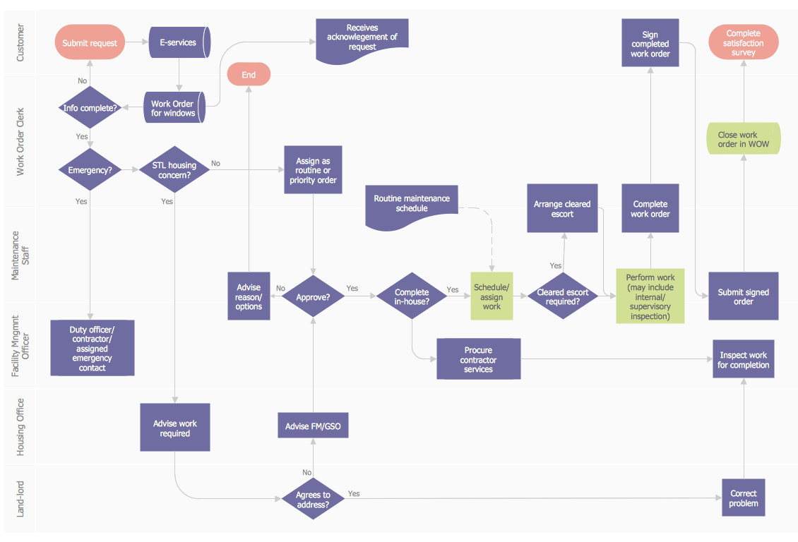
Work Order Process Flowchart. Business Process Mapping Examples
 Wireless Networks
The Wireless Networks Solution extends ConceptDraw DIAGRAM software with professional diagramming tools, set of wireless network diagram templates and samples, comprehensive library of wireless communications and WLAN objects to help network engineers and designers efficiently design and create Wireless network diagrams that illustrate wireless networks of any speed and complexity, and help to identify all required equipment for construction and updating wireless networks, and calculating their costs.
- Draw The Dfd Diagram For Hospital Management System Upto 2 ...
- Level 2 Dfd For Hospital Management System
- Dfd 1level Diagram For Hospital Management System
- Draw A Dfd For Hotel Management System Upto 2 Levels
- Dfd Level 0 Level 1 Level 2 For Project On Hotel Management System
- Level 2 Dfd Hospital Management System
- 0 1 2 Level Dfd For Hospital Management System
- Level O And 1 Dfd Of Hospital Management System
- Zero Level Dfd Of Hospital Management System Project
- Dfd Level 2 Diagram On Hotel Management System
- 0 Level Dfd Of Hospital Management System
- Draw 0 Level Dfd Of Hospital Manangement System
- Draw A Dfd Of 0 1 2 Level For Hospital
- Data Flow Diagram Of Hospital Management System Of 2 Levels
- Hospital Management System Dfd And Context Level
- Data Flow Diagram Of Hospital Billing System
- Draw Context Level Diagram Dfd 1 For Hospital Management System
- Dfd Of Hospital Management System At Level 0
- Hospital Management System Dfd Level 0