Notation & Symbols for ERD

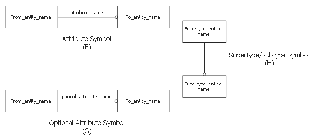
This sample shows EXPRESS-G notation attribute symbols.
This example was drawn on the base of the Wikimedia Commons file: A 02B Attribute symbols.svg. [commons.wikimedia.org/ wiki/ File:A_ 02B_ Attribute_ symbols.svg]
This file is made available under the Creative Commons CC0 1.0 Universal Public Domain Dedication. [creativecommons.org/ publicdomain/ zero/ 1.0/ deed.en]
"Entity attributes allow to add "properties" to entities and to relate one entity with another one in a specific role. The name of the attribute specifies the role. Most datatypes can directly serve as type of an attribute. This includes aggregation as well.
There are three different kinds of attributes, explicit, derived and inverse attributes. And all these can be re-declared in a subtype. In addition an explicit attribute can be re-declared as derived in a subtype. No other change of the kind of attributes is possible.
* Explicit attributes are those with direct values visible in a STEP-File.
* Derived attributes get their values from an expression. In most cases the expression refers to other attributes of THIS instance. The expression may also use EXPRESS functions.
* Inverse attributes do not add "information" to an entity, but only name and constrain an explicit attribute to an entity from the other end." [EXPRESS (data modeling language). Wikipedia]
The EXPRESS-G notation example "EXPRESS-G attribute symbols" was designed using ConceptDraw PRO software extended with EXPRESS-G solution from the Software Development area of ConceptDraw Solution Park.
Data modeling
Anyone Have an ERD Symbols Quick Reference?

ERD Symbols and Meanings


Entity Relationship Diagram Symbols

The vector stencils library "ERD, Chen's notation" contains 13 ERD elements.
Use it for drawing ER-diagrams using Chen's notation in the ConceptDraw PRO diagramming and vector drawing software extended with the Entity-Relationship Diagram (ERD) solution from the Software Development area of ConceptDraw Solution Park.
Use it for drawing ER-diagrams using Chen's notation in the ConceptDraw PRO diagramming and vector drawing software extended with the Entity-Relationship Diagram (ERD) solution from the Software Development area of ConceptDraw Solution Park.
Entity

Weak entity

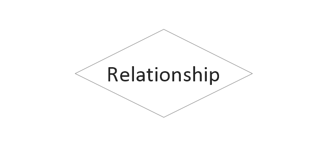
Relationship
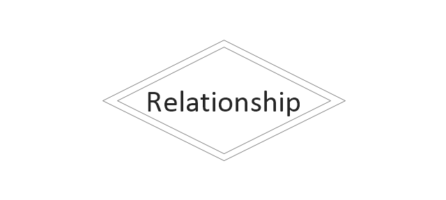
Identifying Relationship
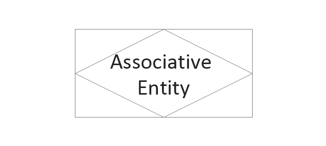
Associative Entity
Participation

Optional participation
Recursive Relationship

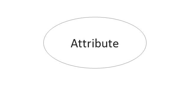
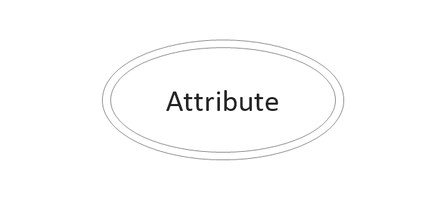
Attribute
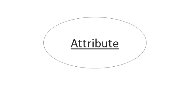
Key attribute
Weak key attribute

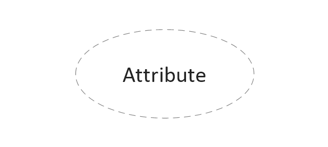
Derived attribute
Multivalue attribute
The vector stencils library "ERD, Chen's notation" contains 13 ERD elements.
Use it for drawing ER-diagrams using Chen's notation in the ConceptDraw PRO diagramming and vector drawing software extended with the Entity-Relationship Diagram (ERD) solution from the Software Development area of ConceptDraw Solution Park.
Use it for drawing ER-diagrams using Chen's notation in the ConceptDraw PRO diagramming and vector drawing software extended with the Entity-Relationship Diagram (ERD) solution from the Software Development area of ConceptDraw Solution Park.
Entity
Weak entity
Relationship
Identifying Relationship
Associative Entity
Participation
Optional participation
Recursive Relationship
Attribute
Key attribute
Weak key attribute
Derived attribute
Multivalue attribute
Database Model Diagram

Cross-Functional Flowchart - The easiest way to draw crossfunctional

How to Simplify Flow Charting — Cross-functional Flowchart

How to Help Customers be More Productive

Electrical Drawing Software and Electrical Symbols

Cross Functional Diagram

Architecture Diagrams

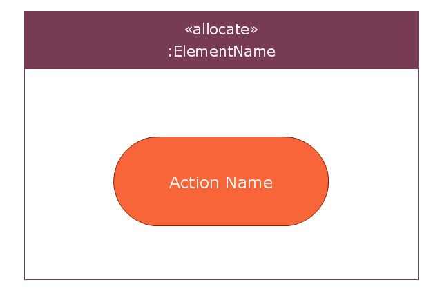
This vector stencils library contains 7 allocation symbols.
Use it to design your SysML diagrams using ConceptDraw PRO diagramming and vector drawing software.
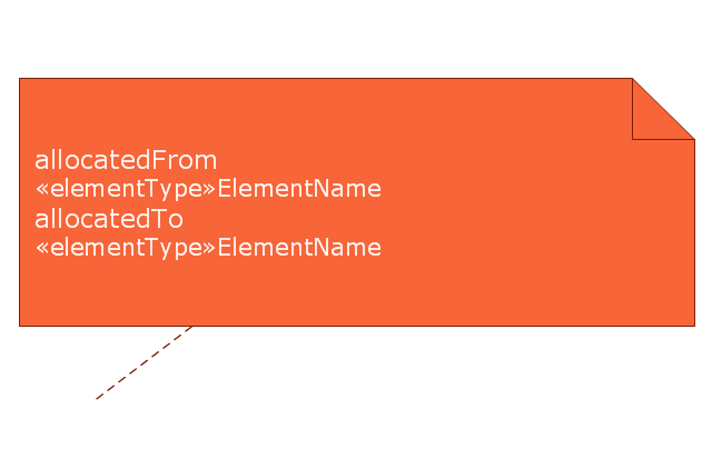
"Allocate is a dependency based on UML::Abstraction. It is a mechanism for associating elements of different types, or in different hierarchies, at an abstract level. Allocate is used for assessing user model consistency and directing future design activity. It is expected that an «allocate» relationship between model elements is a precursor to a more concrete relationship between the elements, their properties, operations, attributes, or sub-classes.
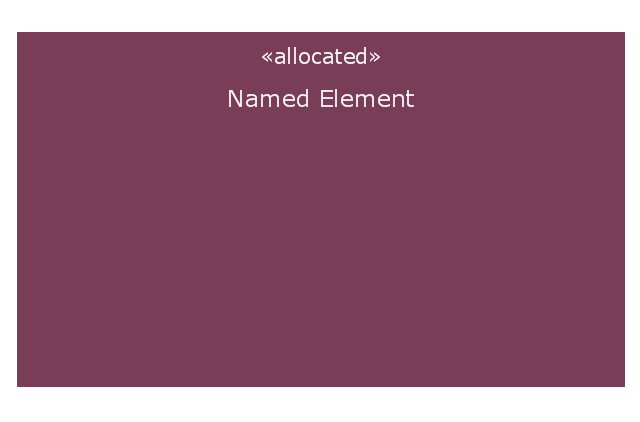
Allocate is a stereotype of a UML4SysML::Abstraction which is permissible between any two NamedElements. It is depicted as a dependency with the “allocate” keyword attached to it.
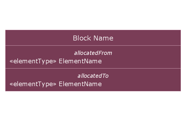
Allocate is directional in that one NamedElement is the “from” end (no arrow), and at least one NamedElement is the “to” end (the end with the arrow)." [www.omg.org/ spec/ SysML/ 1.3/ PDF]
The vector stencils library "Allocations" is included in the SysML solution from the Software Development area of ConceptDraw Solution Park.
Use it to design your SysML diagrams using ConceptDraw PRO diagramming and vector drawing software.
"Allocate is a dependency based on UML::Abstraction. It is a mechanism for associating elements of different types, or in different hierarchies, at an abstract level. Allocate is used for assessing user model consistency and directing future design activity. It is expected that an «allocate» relationship between model elements is a precursor to a more concrete relationship between the elements, their properties, operations, attributes, or sub-classes.
Allocate is a stereotype of a UML4SysML::Abstraction which is permissible between any two NamedElements. It is depicted as a dependency with the “allocate” keyword attached to it.
Allocate is directional in that one NamedElement is the “from” end (no arrow), and at least one NamedElement is the “to” end (the end with the arrow)." [www.omg.org/ spec/ SysML/ 1.3/ PDF]
The vector stencils library "Allocations" is included in the SysML solution from the Software Development area of ConceptDraw Solution Park.
Allocated stereotype
Allocation derived properties in block compartment
Allocation derived properties in comment
Allocation derived properties in part compartment (internal block diagram)
-vector-stencils-library---allocations.png--diagram-flowchart-example.png)
Allocation derived properties in action compartment (activity diagram)
-vector-stencils-library---allocations.png--diagram-flowchart-example.png)
Allocation activity partition
Allocation (general)
-vector-stencils-library---allocations.png--diagram-flowchart-example.png)
The vector stencils library "ERD, Chen's notation" contains 13 ERD elements.
Use it for drawing ER-diagrams using Chen's notation in the ConceptDraw PRO diagramming and vector drawing software extended with the Entity-Relationship Diagram (ERD) solution from the Software Development area of ConceptDraw Solution Park.
Use it for drawing ER-diagrams using Chen's notation in the ConceptDraw PRO diagramming and vector drawing software extended with the Entity-Relationship Diagram (ERD) solution from the Software Development area of ConceptDraw Solution Park.
Entity
Weak entity
Relationship
Identifying Relationship
Associative Entity
Participation
Optional participation
Recursive Relationship
Attribute
Key attribute
Weak key attribute
Derived attribute
Multivalue attribute
UML State Machine Diagram.Design Elements

 EXPRESS-G data Modeling Diagram
EXPRESS-G data Modeling Diagram solution extends the ConceptDraw DIAGRAM software functionality with capabilities of EXPRESS data modeling language, includes powerful data modeling tools, Express-G diagram tool, database diagram tool, database design tool, wide variety of pre-made vector objects of EXPRESS-G notation and EXPRESS-G diagrams samples allowing software developers, software designers, software engineers and other stakeholders to make their data models for information systems, to develop the databases, to learn the principles of construction EXPRESS-G diagrams and helping to draw their own EXPRESS-G Data Modeling Diagrams, Express-G Diagrams or Database Model Diagram without any efforts.
Draw Flowcharts with ConceptDraw

"Chen's notation for entity–relationship modeling uses rectangles to represent entity sets, and diamonds to represent relationships appropriate for first-class objects: they can have attributes and relationships of their own. If an entity set participates in a relationship set, they are connected with a line.
Attributes are drawn as ovals and are connected with a line to exactly one entity or relationship set.
Cardinality constraints are expressed as follows:
- a double line indicates a participation constraint, totality or surjectivity: all entities in the entity set must participate in at least one relationship in the relationship set;
- an arrow from entity set to relationship set indicates a key constraint, i.e. injectivity: each entity of the entity set can participate in at most one relationship in the relationship set;
- a thick line indicates both, i.e. bijectivity: each entity in the entity set is involved in exactly one relationship.
- an underlined name of an attribute indicates that it is a key: two different entities or relationships with this attribute always have different values for this attribute.
Attributes are often omitted as they can clutter up a diagram; other diagram techniques often list entity attributes within the rectangles drawn for entity sets." [Entity–relationship model. Wikipedia]
The vector stencils library ERD, Chen's notation contains 13 symbols for drawing entity-relatinship diagrams using the ConceptDraw PRO diagramming and vector drawing software.
The example "Design elements - ER diagram (Chen notation)" is included in the Entity-Relationship Diagram (ERD) solution from the Software Development area of ConceptDraw Solution Park.
Chen's ERD
.png--diagram-flowchart-example.png)
- Entity Relationship Diagram Symbols | Derived Attribute
- Entity Relationship Diagram Symbols | ERD Symbols and Meanings ...
- Entity Relationship Diagram Symbols | Erd Derived Attribute
- MS Visio Look a Like Diagrams | Derived Attribute Shape
- ERD, Chen's notation | Derived Attributes In Er Diagram
- ERD, Chen's notation - Vector stencils library | ERD, Chen's notation ...
- Basic Flowchart Symbols and Meaning | Which Symbol Denotoes ...
- ERD Symbols and Meanings | Attribute
- Entity Relationship Diagram Symbols | Multivalued Attribute In Visio
- Visio Files and ConceptDraw | Meaning Of Weak Key Attribute