ERD Symbols and Meanings


Entity Relationship Diagram Symbols

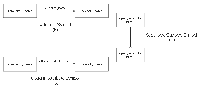
This sample shows EXPRESS-G notation attribute symbols.
This example was drawn on the base of the Wikimedia Commons file: A 02B Attribute symbols.svg. [commons.wikimedia.org/ wiki/ File:A_ 02B_ Attribute_ symbols.svg]
This file is made available under the Creative Commons CC0 1.0 Universal Public Domain Dedication. [creativecommons.org/ publicdomain/ zero/ 1.0/ deed.en]
"Entity attributes allow to add "properties" to entities and to relate one entity with another one in a specific role. The name of the attribute specifies the role. Most datatypes can directly serve as type of an attribute. This includes aggregation as well.
There are three different kinds of attributes, explicit, derived and inverse attributes. And all these can be re-declared in a subtype. In addition an explicit attribute can be re-declared as derived in a subtype. No other change of the kind of attributes is possible.
* Explicit attributes are those with direct values visible in a STEP-File.
* Derived attributes get their values from an expression. In most cases the expression refers to other attributes of THIS instance. The expression may also use EXPRESS functions.
* Inverse attributes do not add "information" to an entity, but only name and constrain an explicit attribute to an entity from the other end." [EXPRESS (data modeling language). Wikipedia]
The EXPRESS-G notation example "EXPRESS-G attribute symbols" was designed using ConceptDraw PRO software extended with EXPRESS-G solution from the Software Development area of ConceptDraw Solution Park.
Data modeling
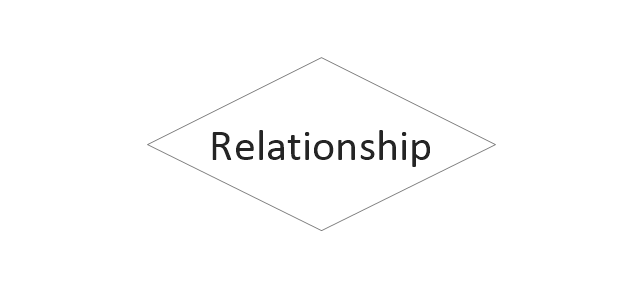
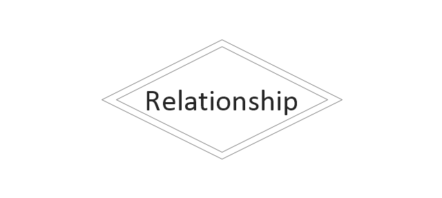
"Chen's notation for entity–relationship modeling uses rectangles to represent entity sets, and diamonds to represent relationships appropriate for first-class objects: they can have attributes and relationships of their own. If an entity set participates in a relationship set, they are connected with a line.
Attributes are drawn as ovals and are connected with a line to exactly one entity or relationship set.
Cardinality constraints are expressed as follows:
- a double line indicates a participation constraint, totality or surjectivity: all entities in the entity set must participate in at least one relationship in the relationship set;
- an arrow from entity set to relationship set indicates a key constraint, i.e. injectivity: each entity of the entity set can participate in at most one relationship in the relationship set;
- a thick line indicates both, i.e. bijectivity: each entity in the entity set is involved in exactly one relationship.
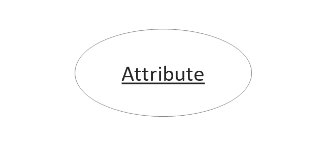
- an underlined name of an attribute indicates that it is a key: two different entities or relationships with this attribute always have different values for this attribute.
Attributes are often omitted as they can clutter up a diagram; other diagram techniques often list entity attributes within the rectangles drawn for entity sets." [Entity–relationship model. Wikipedia]
The vector stencils library ERD, Chen's notation contains 13 symbols for drawing entity-relatinship diagrams using the ConceptDraw PRO diagramming and vector drawing software.
The example "Design elements - ER diagram (Chen notation)" is included in the Entity-Relationship Diagram (ERD) solution from the Software Development area of ConceptDraw Solution Park.
Attributes are drawn as ovals and are connected with a line to exactly one entity or relationship set.
Cardinality constraints are expressed as follows:
- a double line indicates a participation constraint, totality or surjectivity: all entities in the entity set must participate in at least one relationship in the relationship set;
- an arrow from entity set to relationship set indicates a key constraint, i.e. injectivity: each entity of the entity set can participate in at most one relationship in the relationship set;
- a thick line indicates both, i.e. bijectivity: each entity in the entity set is involved in exactly one relationship.
- an underlined name of an attribute indicates that it is a key: two different entities or relationships with this attribute always have different values for this attribute.
Attributes are often omitted as they can clutter up a diagram; other diagram techniques often list entity attributes within the rectangles drawn for entity sets." [Entity–relationship model. Wikipedia]
The vector stencils library ERD, Chen's notation contains 13 symbols for drawing entity-relatinship diagrams using the ConceptDraw PRO diagramming and vector drawing software.
The example "Design elements - ER diagram (Chen notation)" is included in the Entity-Relationship Diagram (ERD) solution from the Software Development area of ConceptDraw Solution Park.
Chen's ERD
.png--diagram-flowchart-example.png)
The vector stencils library "ERD, Chen's notation" contains 13 ERD elements.
Use it for drawing ER-diagrams using Chen's notation in the ConceptDraw PRO diagramming and vector drawing software extended with the Entity-Relationship Diagram (ERD) solution from the Software Development area of ConceptDraw Solution Park.
Use it for drawing ER-diagrams using Chen's notation in the ConceptDraw PRO diagramming and vector drawing software extended with the Entity-Relationship Diagram (ERD) solution from the Software Development area of ConceptDraw Solution Park.
Entity

Weak entity

Relationship
Identifying Relationship
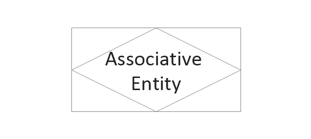
Associative Entity
Participation

Optional participation
Recursive Relationship

Attribute
Key attribute
Weak key attribute

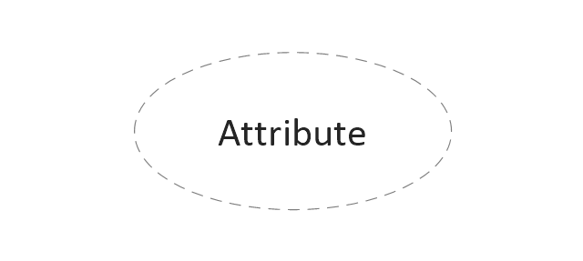
Derived attribute
Multivalue attribute
The vector stencils library "ERD, Chen's notation" contains 13 ERD elements.
Use it for drawing ER-diagrams using Chen's notation in the ConceptDraw PRO diagramming and vector drawing software extended with the Entity-Relationship Diagram (ERD) solution from the Software Development area of ConceptDraw Solution Park.
Use it for drawing ER-diagrams using Chen's notation in the ConceptDraw PRO diagramming and vector drawing software extended with the Entity-Relationship Diagram (ERD) solution from the Software Development area of ConceptDraw Solution Park.
Entity
Weak entity
Relationship
Identifying Relationship
Associative Entity
Participation
Optional participation
Recursive Relationship
Attribute
Key attribute
Weak key attribute
Derived attribute
Multivalue attribute
ConceptDraw DIAGRAM ER Diagram Tool

Notation & Symbols for ERD

The vector stencils library "AWS Database" contains 30 Amazon Web Services database icons: Amazon DynamoDB symbols, Amazon Relational Database Service symbols, Amazon ElasticCache symbols, Amazon SimpleDB symbols, Amazon Redshift symbols.
Use it to draw AWS architecture diagrams of your cloud service.
The symbols example "AWS Database - Vector stencils library" was created using the ConceptDraw PRO diagramming and vector drawing software extended with the AWS Architecture Diagrams solution from the Computer and Networks area of ConceptDraw Solution Park.
DynamoDB

Table
Item

Items
Attribute

Attributes

Global secondary index

Amazon RDS

RDS DB instance
RDS DB instance standby (Multi-AZ)
-aws-database---vector-stencils-library.png--diagram-flowchart-example.png)
RDS DB instance read replica
MySQL DB instance
Oracle DB instance
MS SQL
instance
PostgreSQL instance
SQL master

SQL slave
PIOP
ElastiCache

Cache node
Redis

Memcached

Amazon SimpleDB

Domain
Amazon Redshift

Solid state disks

DW2 Dense Compute
DW1 Dense Compute

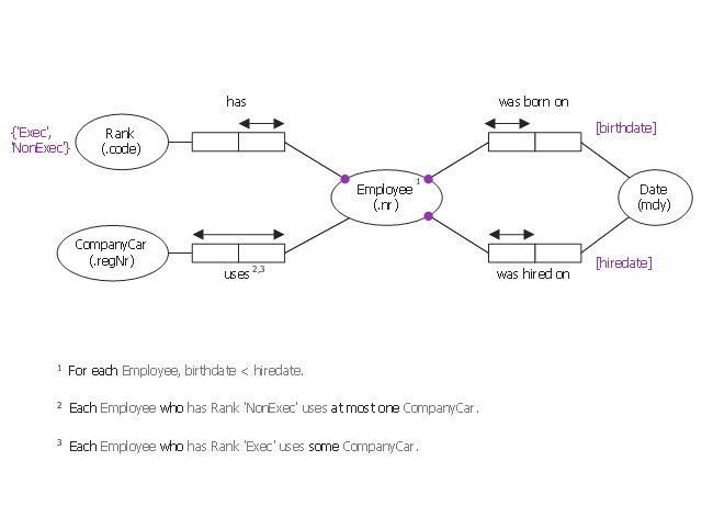
This object-role modeling (ORM) diagram sample shows model of employee data: birthdate, hiredate, rank, company car number. It was designed on the base of the Wikimedia Commons file: ORM-diagram-tkz-orm.png. [commons.wikimedia.org/ wiki/ File:ORM-diagram-tkz-orm.png]
"Facts.
Object-role models are based on elementary facts, and expressed in diagrams that can be verbalised into natural language. ...
This "fact-based" approach facilitates modeling, transforming, and querying information from any domain. ...
Attribute-free.
ORM is attribute-free: unlike models in the entity–relationship (ER) and Unified Modeling Language (UML) methods, ORM treats all elementary facts as relationships and so treats decisions for grouping facts into structures (e.g. attribute-based entity types, classes, relation schemes, XML schemas) as implementation concerns irrelevant to semantics. By avoiding attributes in the base model, ORM improves semantic stability and enables verbalization into natural language. ...
Fact-based modeling.
Fact-based modeling includes procedures for mapping facts to attribute-based structures, such as those of ER or UML. ...
Fact-based graphical notations are more expressive than those of ER and UML. ...
Design procedure.
System development typically involves several stages such as: feasibility study; requirements analysis; conceptual design of data and operations; logical design; external design; prototyping; internal design and implementation; testing and validation; and maintenance." [Object-role modeling. Wikipedia]
The object-role modeling diagram example "Employee ORM diagram" was designed using ConceptDraw PRO software extended with ORM Diagrams solution from Software Development area of ConceptDraw PRO Solution Park.
Object-role model
"In software engineering, an entity–relationship model (ER model) is a data model for describing a database in an abstract way.Chen's notation for entity–relationship modeling uses rectangles to represent entity sets, and diamonds to represent relationships appropriate for first-class objects: they can have attributes and relationships of their own. If an entity set participates in a relationship set, they are connected with a line.
Attributes are drawn as ovals and are connected with a line to exactly one entity or relationship set." [Entity–relationship model. Wikipedia]
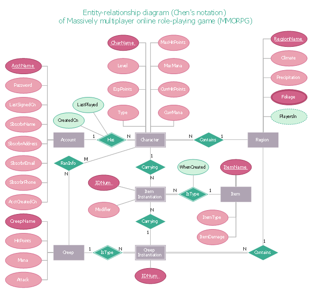
This sample Chen's ER-diagram illustrates the structure of a typical MMORP game.
"Massively multiplayer online role-playing game (MMORPG) mixes the genres of role-playing video games and Massively multiplayer online games, possibly in the form of web browser-based games, in which a very large number of players interact with one another within a virtual world.
As in all RPGs, players assume the role of a character (often in a fantasy world or science-fiction world) and take control over many of that character's actions. MMORPGs are distinguished from single-player or small multi-player online RPGs by the number of players, and by the game's persistent world (usually hosted by the game's publisher), which continues to exist and evolve while the player is offline and away from the game." [Massively multiplayer online role-playing game. Wikipedia]
This ERD example was redrawn using the ConceptDraw PRO diagramming and vector drawing software from the Wikipedia file: ER Diagram MMORPG.png. [en.wikipedia.org/ wiki/ File:ER_ Diagram_ MMORPG.png]
This file is licensed under the Creative Commons Attribution-Share Alike 3.0 Unported license. [creativecommons.org/ licenses/ by-sa/ 3.0/ deed.en]
This Chen's ERD example is included in the Entity-Relationship Diagram (ERD) solution from the Software Development area of ConceptDraw Solution Park.
Attributes are drawn as ovals and are connected with a line to exactly one entity or relationship set." [Entity–relationship model. Wikipedia]
This sample Chen's ER-diagram illustrates the structure of a typical MMORP game.
"Massively multiplayer online role-playing game (MMORPG) mixes the genres of role-playing video games and Massively multiplayer online games, possibly in the form of web browser-based games, in which a very large number of players interact with one another within a virtual world.
As in all RPGs, players assume the role of a character (often in a fantasy world or science-fiction world) and take control over many of that character's actions. MMORPGs are distinguished from single-player or small multi-player online RPGs by the number of players, and by the game's persistent world (usually hosted by the game's publisher), which continues to exist and evolve while the player is offline and away from the game." [Massively multiplayer online role-playing game. Wikipedia]
This ERD example was redrawn using the ConceptDraw PRO diagramming and vector drawing software from the Wikipedia file: ER Diagram MMORPG.png. [en.wikipedia.org/ wiki/ File:ER_ Diagram_ MMORPG.png]
This file is licensed under the Creative Commons Attribution-Share Alike 3.0 Unported license. [creativecommons.org/ licenses/ by-sa/ 3.0/ deed.en]
This Chen's ERD example is included in the Entity-Relationship Diagram (ERD) solution from the Software Development area of ConceptDraw Solution Park.
Chen's ERD
Design Element: Chen for Entity Relationship Diagram - ERD

Anyone Have an ERD Symbols Quick Reference?

The vector stencils library "Bank UML object diagram" contains 11 shapes for drawing UML object diagrams.
Use it for object-oriented modeling of your bank information system.
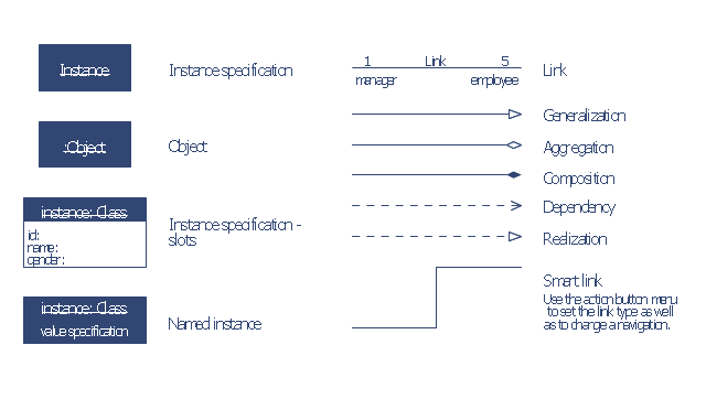
"In the Unified Modeling Language (UML), an object diagram focuses on some particular set of objects and attributes, and the links between these instances. A correlated set of object diagrams provides insight into how an arbitrary view of a system is expected to evolve over time. ...
Each object and link on an object diagram is represented by an InstanceSpecification. This can show an object's classifier (e.g. an abstract or concrete class) and instance name, as well as attributes and other structural features using slots. Each slot corresponds to a single attribute or feature, and may include a value for that entity. ...
The name on an instance specification optionally shows an instance name, a ':' separator, and optionally one or more classifier names separated by commas. The contents of slots, if any, are included below the names, in a separate attribute compartment. A link is shown as a solid line, and represents an instance of an association. ...
An object instance may be called an instance specification or just an instance. A link between instances is generally referred to as a link. Other UML entities, such as an aggregation or composition symbol (a diamond) may also appear on an object diagram." [Object diagram. Wikipedia]
This example of UML object diagram symbols for the ConceptDraw PRO diagramming and vector drawing software is included in the ATM UML Diagrams solution from the Software Development area of ConceptDraw Solution Park.
Use it for object-oriented modeling of your bank information system.
"In the Unified Modeling Language (UML), an object diagram focuses on some particular set of objects and attributes, and the links between these instances. A correlated set of object diagrams provides insight into how an arbitrary view of a system is expected to evolve over time. ...
Each object and link on an object diagram is represented by an InstanceSpecification. This can show an object's classifier (e.g. an abstract or concrete class) and instance name, as well as attributes and other structural features using slots. Each slot corresponds to a single attribute or feature, and may include a value for that entity. ...
The name on an instance specification optionally shows an instance name, a ':' separator, and optionally one or more classifier names separated by commas. The contents of slots, if any, are included below the names, in a separate attribute compartment. A link is shown as a solid line, and represents an instance of an association. ...
An object instance may be called an instance specification or just an instance. A link between instances is generally referred to as a link. Other UML entities, such as an aggregation or composition symbol (a diamond) may also appear on an object diagram." [Object diagram. Wikipedia]
This example of UML object diagram symbols for the ConceptDraw PRO diagramming and vector drawing software is included in the ATM UML Diagrams solution from the Software Development area of ConceptDraw Solution Park.
UML object diagram symbols
ConceptDraw DIAGRAM : Able to Leap Tall Buildings in a Single Bound

The vector stencils library "ERD, Chen's notation" contains 13 ERD elements.
Use it for drawing ER-diagrams using Chen's notation in the ConceptDraw PRO diagramming and vector drawing software extended with the Entity-Relationship Diagram (ERD) solution from the Software Development area of ConceptDraw Solution Park.
Use it for drawing ER-diagrams using Chen's notation in the ConceptDraw PRO diagramming and vector drawing software extended with the Entity-Relationship Diagram (ERD) solution from the Software Development area of ConceptDraw Solution Park.
Entity
Weak entity
Relationship
Identifying Relationship
Associative Entity
Participation
Optional participation
Recursive Relationship
Attribute
Key attribute
Weak key attribute
Derived attribute
Multivalue attribute
The vector stencils library "AWS Database" contains 30 Amazon Web Services database icons: Amazon DynamoDB symbols, Amazon Relational Database Service symbols, Amazon ElasticCache symbols, Amazon SimpleDB symbols, Amazon Redshift symbols.
Use it to draw AWS architecture diagrams of your cloud service.
The symbols example "AWS Database - Vector stencils library" was created using the ConceptDraw PRO diagramming and vector drawing software extended with the AWS Architecture Diagrams solution from the Computer and Networks area of ConceptDraw Solution Park.
Use it to draw AWS architecture diagrams of your cloud service.
The symbols example "AWS Database - Vector stencils library" was created using the ConceptDraw PRO diagramming and vector drawing software extended with the AWS Architecture Diagrams solution from the Computer and Networks area of ConceptDraw Solution Park.
DynamoDB
Table
Item
Items
Attribute
Attributes
Global secondary index
Amazon RDS
RDS DB instance
RDS DB instance standby (Multi-AZ)
RDS DB instance read replica
MySQL DB instance
Oracle DB instance
MS SQL
instance
PostgreSQL instance
SQL master
SQL slave
PIOP
ElastiCache
Cache node
Redis
Memcached
Amazon SimpleDB
Domain
Amazon Redshift
Solid state disks
DW2 Dense Compute
DW1 Dense Compute
- ERD, Chen's notation - Vector stencils library | ERD Symbols and ...
- ERD, Chen's notation - Vector stencils library | ERD, Chen's notation ...
- How To Represent Unique Attribute In Er Diagram
- ERD Symbols and Meanings | Entity Relationship Diagram Symbols ...
- Erd Derived Attribute
- Er Diagram Optional Attribute
- Entity Relationship Diagram Symbols | ERD Symbols and Meanings ...
- How To Make Chen ER Diagram | Entity Relationship Diagram ...
- ERD, Chen's notation - Vector stencils library
- ERD, Chen's notation - Vector stencils library
- ERD, Chen's notation - Vector stencils library
- ERD, Chen's notation - Vector stencils library
- Design elements - ER diagram (Chen notation) | Entity Relationship ...
- Design elements - ER diagram (Chen notation) | Chen Notation ...
- ERD, Chen's notation - Vector stencils library | ERD, Chen's notation ...
- Entity-Relationship Diagram (ERD) | Design elements - ER diagram ...
- Symbol Of Multivalued Attribute In Er Diagram
- AWS Database - Vector stencils library
- Design elements - ER diagram (Chen notation) | Design elements ...
- Design elements - ER diagram (Chen notation) | Entity-Relationship ...