Structured Systems Analysis and Design Method (SSADM) with ConceptDraw PRO

Process Flowchart


Types of Flowcharts


IDEF9 Standard

IDEF4 Standard

HelpDesk
How to Work with Custom Properties

HelpDesk
How to Create a New Library

HelpDesk
How to Make Different Backgrounds Within a Multipage Drawing

GUI Prototyping with ConceptDraw PRO

 PM Easy
PM Easy solution extends the ConceptDraw PROJECT functionality with an ability to support neutral methodology of project management and to quickly start a project by listing the task relationships and dependencies, that makes the iterative planning much easier. The project management tool and available visual tools, such as mind mapping, increase the effectiveness of tracking and analysis your project tasks. PM Easy solution from ConceptDraw Solution Park is mainly targeted at project managers in small or medium-sized companies, allowing them to make the project plan and execute projects using mind mapping technique, to implement planning using mind mapping, and to track tasks using ConceptDraw PROJECT application.
HelpDesk
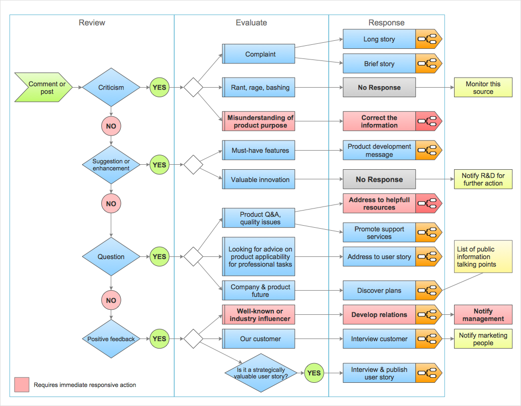
How to Organize a Social Media Activity
Scrum process work items and workflow

The vector stencils library "Process annotations" contains 22 symbols of interface points, slope, off-sheet labels, callouts and textboxes.
Use these shapes for setting automatic labels to display a datasheet field for a pipeline shape, labels, captions, outlines, off-sheet labels, text balloons, annotations, outlines, tags, and descriptions.
"In engineering a process is a set of interrelated tasks that, together, transform inputs into outputs. These tasks may be carried out by people, nature, or machines using resources; so an engineering process must be considered in the context of the agents carrying out the tasks, and the resource attributes involved. Systems Engineering normative documents and those related to Maturity Models are typically based on processes. For example, System Engineering processes of the EIA-632 and processes involved in the Capability Maturity Model Integration (CMMI) institutionalization and improvement approach. Constraints imposed on the tasks and resources required to implement them are essential for executing the tasks mentioned.
A chemical process is a series of unit operations used to produce a material in large quantities.
In the chemical industry, chemical engineers will use the following to define or illustrate a process:
Process Flow Diagram (PFD),
Piping and instrumentation diagram
(P&ID),
Simplified process description,
Detailed process description,
Project management,
Process simulation." [Process (engineering). Wikipedia]
The example "Design elements - Process annotations" was created using the ConceptDraw PRO diagramming and vector drawing software extended with the Chemical and Process Engineering solution from the Engineering area of ConceptDraw Solution Park.
Process annotation symbols

- System Context Diagram
- Define Data Flow Diagram Library
- Data Flow Diagram Symbols. DFD Library | Basic Flowchart ...
- Data Flow Diagram (DFD)
- Structured Systems Analysis and Design Method (SSADM) with ...
- Gane Sarson Diagram | DFD, Gane-Sarson notation - Template ...
- Gane Sarson Diagram | DFD, Gane-Sarson notation - Template ...
- Process Flow Diagram For Account
- DFD Library - Design elements | Design Data Flow . DFD Library ...
- Dfd Diagram Design Shapes Define
- Data Flow Diagram
- Types of Flowcharts | Basic Flowchart Symbols and Meaning ...
- Types of Flowcharts | ORM Diagram | Define And Draw Gane And ...
- Cisco Network Templates | Workflow Diagram Template | Context ...
- DFD Library System | Data Flow Diagram Symbols. DFD Library ...
- DFD Library System | Data Flow Diagram Symbols. DFD Library ...
- Basic Flowchart Symbols and Meaning | Data Flow Diagrams | Visio ...
- Data flow Model Diagram
- Entity Relationship Diagram Symbols | Basic Flowchart Symbols and ...
- Data Flow Diagram Model | Process Flowchart | Process Flow Maps ...