HelpDesk
How to Create a Bank ATM Use Case Diagram

Use Case Diagrams technology with ConceptDraw DIAGRAM

UML Use Case Diagram Example. Registration System

Financial Trade UML Use Case Diagram Example

UML Use Case Diagram Example. Social Networking Sites Project

UML Use Case Diagram Example - Estate Agency

UML Use Case Diagram Example - Taxi Service

UML Use Case Diagram Example. Services UML Diagram. ATM system

Jacobson Use Cases Diagram

UML Diagrams with ConceptDraw DIAGRAM

This example of bank ATM UML activity diagram was created on the base of UML use case diagram of automated teller machine from the course "Thinking in Java, 2nd edition, Revision 9" by Bruce Eckel published on the website of the Computer Science and Electrical Engineering Department of the University of Maryland, Baltimore (UMBC).
"If you are designing an auto-teller, for example, the use case for a particular aspect of the functionality of the system is able to describe what the auto-teller does in every possible situation. Each of these “situations” is referred to as a scenario, and a use case can be considered a collection of scenarios. You can think of a scenario as a question that starts with: “What does the system do if...?” For example, “What does the auto-teller do if a customer has just deposited a check within the last 24 hours, and there’s not enough in the account without the check having cleared to provide a desired withdrawal?”
Use case diagrams are intentionally simple to prevent you from getting bogged down in system implementation details prematurely...
Each stick person represents an “actor,” which is typically a human or some other kind of free agent. (These can even be other computer systems, as is the case with “ATM.”) The box represents the boundary of your system. The ellipses represent the use cases, which are descriptions of valuable work that can be performed with the system. The lines between the actors and the use cases represent the interactions.
It doesn’t matter how the system is actually implemented, as long as it looks like this to the user."
[csee.umbc.edu/ courses/ 331/ resources/ tij/ text/ TIJ213.gif]
This automated teller machine (ATM) UML use case diagram example was created using the ConceptDraw PRO diagramming and vector drawing software extended with the ATM UML Diagrams solution from the Software Development area of ConceptDraw Solution Park.
Bank ATM UML sequence diagram

Flowchart Components

"Banks offer many different channels to access their banking and other services:
(1) Automated Teller Machines.
(2) A branch is a retail location.
(3) Call center.
(4) Mail: most banks accept cheque deposits via mail and use mail to communicate to their customers, e.g. by sending out statements.
(5) Mobile banking is a method of using one's mobile phone to conduct banking transactions.
(6) Online banking is a term used for performing multiple transactions, payments etc. over the Internet.
(7) Relationship Managers, mostly for private banking or business banking, often visiting customers at their homes or businesses.
(8) Telephone banking is a service which allows its customers to conduct transactions over the telephone with automated attendant or when requested with telephone operator.
(9) Video banking is a term used for performing banking transactions or professional banking consultations via a remote video and audio connection. Video banking can be performed via purpose built banking transaction machines (similar to an Automated teller machine), or via a video conference enabled bank branch clarification.
(10) DSA is a Direct Selling Agent, who works for the bank based on a contract. Its main job is to increase the customer base for the bank." [Bank. Wikipedia]
The UML use case diagram example "Banking system" was created using the ConceptDraw PRO diagramming and vector drawing software extended with the Rapid UML solution from the Software Development area of ConceptDraw Solution Park.
UML use case diagram

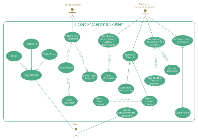
"An example scenario is presented to demonstrate how a common issue tracking system would work:
(1) A customer service technician receives a telephone call, email, or other communication from a customer about a problem. Some applications provide built-in messaging system and automatic error reporting from exception handling blocks.
(2) The technician verifies that the problem is real, and not just perceived. The technician will also ensure that enough information about the problem is obtained from the customer. This information generally includes the environment of the customer, when and how the issue occurs, and all other relevant circumstances.
(3) The technician creates the issue in the system, entering all relevant data, as provided by the customer.
(4) As work is done on that issue, the system is updated with new data by the technician. Any attempt at fixing the problem should be noted in the issue system. Ticket status most likely will be changed from open to pending.
(5) After the issue has been fully addressed, it is marked as resolved in the issue tracking system.
If the problem is not fully resolved, the ticket will be reopened once the technician receives new information from the customer. A Run Book Automation process that implements best practices for these workflows and increases IT personnel effectiveness is becoming very common." [Issue tracking system. Wikipedia]
The UML use case diagram example "Ticket processing system" was created using the ConceptDraw PRO diagramming and vector drawing software extended with the Rapid UML solution from the Software Development area of ConceptDraw Solution Park.
UML use case diagram
UML Use Case Diagram. Design Elements


Create UML Diagram

How To Create a Workflow Diagram

UML Class Diagram Generalization Example UML Diagrams

Online Diagram Tool

Easy Flowchart Software

- Financial Trade UML Use Case Diagram Example | How to create a ...
- UML use case diagram - Banking system | How to Create a Bank ...
- UML use case diagram - Banking system | How to Create a Bank ...
- Bank ATM use case diagram | How to Create a Bank ATM Use Case ...
- How to Create a Bank ATM Use Case Diagram | Use Case ...
- UML Use Case Diagram Example. Registration System | Jacobson ...
- UML Use Case Diagram Example. Registration System
- UML Use Case Diagram Example Social Networking Sites Project ...
- UML Use Case Diagram Example. Services UML Diagram. ATM ...
- How To Create a Workflow Diagram | UML Use Case Diagram ...
- How to Create a Bank ATM Use Case Diagram | UML Use Case ...
- Diagramming Software for Design UML Use Case Diagrams | UML ...
- UML Diagram of Parking | UML Use Case Diagram Example. Social ...
- Use Case Diagram For Online Banking System
- UML Use Case Diagram Example. Registration System | UML ...
- UML Use Case Diagram Example Registration System | UML activity ...
- How to Create a Bank ATM Use Case Diagram | Use Case ...
- UML Use Case Diagram Example Registration System | How to ...
- UML Use Case Diagram Example. Registration System | Financial ...
- Bank Sequence Diagram | UML use case diagram - Banking system ...