Electrical Symbols, Electrical Diagram Symbols

"The symbols and conventions used in welding documentation are specified in national and international standards such as ISO 2553 Welded, brazed and soldered joints -- Symbolic representation on drawings and ISO 4063 Welding and allied processes -- Nomenclature of processes and reference numbers. The US standard symbols are outlined by the American National Standards Institute and the American Welding Society and are noted as "ANSI/ AWS".
In engineering drawings, each weld is conventionally identified by an arrow which points to the joint to be welded. The arrow is annotated with letters, numbers and symbols which indicate the exact specification of the weld. In complex applications, such as those involving alloys other than mild steel, more information may be called for than can comfortably be indicated using the symbols alone. Annotations are used in these cases." [Symbols and conventions used in welding documentation. Wikipedia]
The example chart "Elements of welding symbol" is redesigned using the ConceptDraw PRO diagramming and vector drawing software from the Wikipedia file: Elements of a welding symbol.PNG.
[en.wikipedia.org/ wiki/ File:Elements_ of_ a_ welding_ symbol.PNG]
The diagram example "Elements location of a welding symbol" is contained in the Mechanical Engineering solution from the Engineering area of ConceptDraw Solution Park.
Welding joint symbol chart

Process Flow Diagram Symbols

SysML Diagram

Electrical Symbols — Qualifying

Electrical Symbols — IGFET

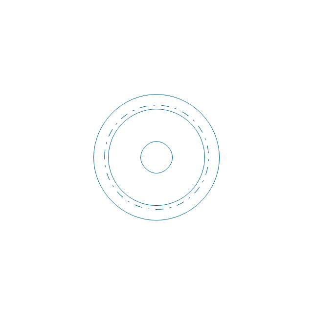
The vector stencils library "Bearings" contains 59 symbols of ball bearings, roller bearings, shafts, springs, gears, hooks, spindles, and keys.
Use it to design engineering drawings of machine tools and mechanical devices.
"A bearing is a machine element that constrains relative motion and reduce friction between moving parts to only the desired motion. The design of the bearing may, for example, provide for free linear movement of the moving part or for free rotation around a fixed axis; or, it may prevent a motion by controlling the vectors of normal forces that bear on the moving parts. Many bearings also facilitate the desired motion as much as possible, such as by minimizing friction. Bearings are classified broadly according to the type of operation, the motions allowed, or to the directions of the loads (forces) applied to the parts." [Bearing (mechanical). Wikipedia]
The shapes example "Design elements - Bearings" was created using the ConceptDraw PRO diagramming and vector drawing software extended with the Mechanical Engineering solution from the Engineering area of ConceptDraw Solution Park.
Bearing symbols

Value stream with ConceptDraw DIAGRAM

The vector stencils library "Analog and digital logic" contains 40 element symbols of logic (threshold) gates, bistable current switches, current controllers, regulators, electrical generators, and amplifiers.
Use it for drawing the digital and analog functions in electronic circuit diagrams and electrical schematics.
"Analogue electronics (or analog in American English) are electronic systems with a continuously variable signal, in contrast to digital electronics where signals usually take only two different levels. The term "analogue" describes the proportional relationship between a signal and a voltage or current that represents the signal." [Analogue electronics. Wikipedia]
"Digital electronics, or digital (electronic) circuits, represent signals by discrete bands of analog levels, rather than by a continuous range. All levels within a band represent the same signal state. Relatively small changes to the analog signal levels due to manufacturing tolerance, signal attenuation or parasitic noise do not leave the discrete envelope, and as a result are ignored by signal state sensing circuitry.
In most cases the number of these states is two, and they are represented by two voltage bands: one near a reference value (typically termed as "ground" or zero volts) and a value near the supply voltage, corresponding to the "false" ("0") and "true" ("1") values of the Boolean domain respectively.
Digital techniques are useful because it is easier to get an electronic device to switch into one of a number of known states than to accurately reproduce a continuous range of values.
Digital electronic circuits are usually made from large assemblies of logic gates, simple electronic representations of Boolean logic functions." [Digital electronics. Wikipedia]
The example "Design elements - Analog and digital logic" was drawn using the ConceptDraw PRO diagramming and vector drawing software extended with the Electrical Engineering solution from the Engineering area of ConceptDraw Solution Park.
Analog and digital logic elements

Value Stream Mapping Icons
Flow Chart Online

 Flowcharts
The Flowcharts solution for ConceptDraw DIAGRAM is a comprehensive set of examples and samples in several varied color themes for professionals that need to represent graphically a process. Solution value is added by the basic flow chart template and shapes' libraries of flowchart notation. ConceptDraw DIAGRAM flow chart creator lets one depict the processes of any complexity and length, as well as design the Flowchart either vertically or horizontally.
Seven Basic Tools of Quality — Quality Control

UML Diagram Editor

3D Network Diagram Software


F&B

The design elements library Walls, shell and structure contains 29 symbols of structural elements: walls, rooms, windows, doors, pillars.
Use the vector stencils library Walls, shell and structure to draw the floor plans and other architectural drawings, blueprints, home and building interior design, space layout plans, construction and house framing diagrams using the ConceptDraw PRO diagramming and vector drawing software.
"A wall is a horizontal structure, usually solid, that defines and sometimes protects an area. Most commonly, a wall delineates a building and supports its superstructure, separates space in buildings into sections, or protects or delineates a space in the open air. There are three principal types of structural walls: building walls, exterior boundary walls, and retaining walls.
Building walls have one main purpose: to support roofs and ceilings. Such walls most often have three or more separate components. In today's construction, a building wall will usually have the structural elements (such as 2×4 studs in a house wall), insulation, and finish elements or surface (such as drywall or panelling). In addition, the wall may house various types of electrical wiring or plumbing. Electrical outlets are usually mounted in walls.
Building walls frequently become works of art externally and internally, such as when featuring mosaic work or when murals are painted on them; or as design foci when they exhibit textures or painted finishes for effect.
In architecture and civil engineering, the term curtain wall refers to the facade of a building which is not load-bearing but functions as decoration, finish, front, face, or history preservation." [Wall. Wikipedia]
This shapes library Walls, shell and structure is provided by the Floor Plans solution from the Building Plans area of ConceptDraw Solution Park.

The vector stencils library "Bearings" contains 59 symbols of ball bearings, roller bearings, shafts, springs, gears, hooks, spindles, and keys.
Use it to design engineering drawings of machine tools and mechanical devices in the ConceptDraw PRO diagramming and vector drawing software extended with the Mechanical Engineering solution from the Engineering area of ConceptDraw Solution Park.
www.conceptdraw.com/ solution-park/ engineering-mechanical
Through hole
Threaded hole 3
Threaded hole 4
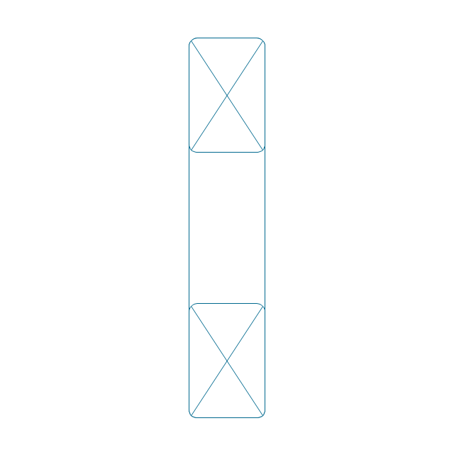
Rolling bearings 2
Rolling bearings
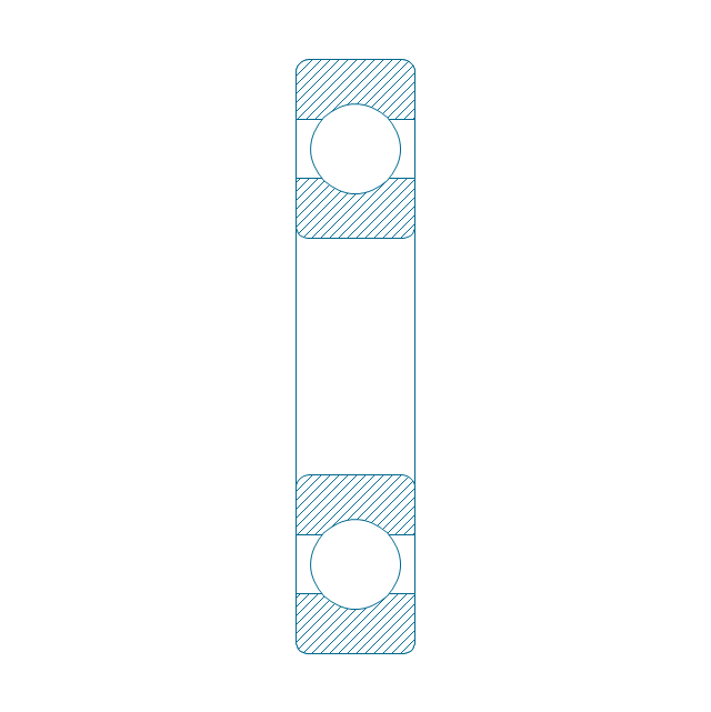
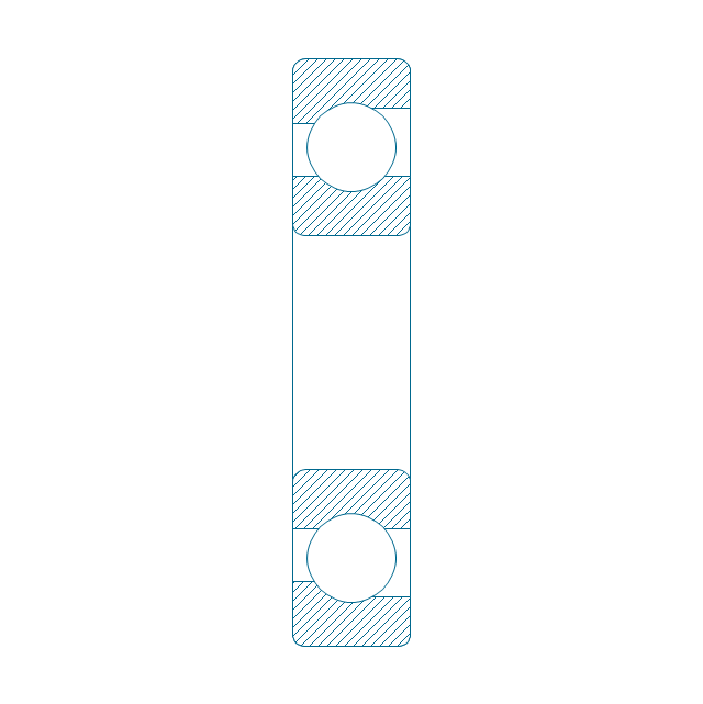
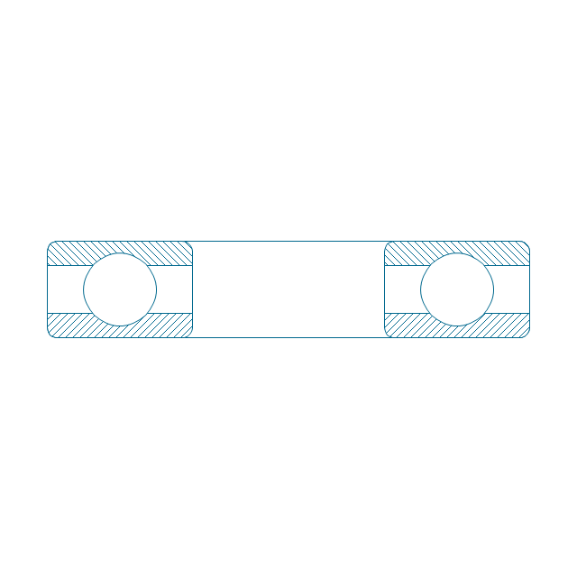
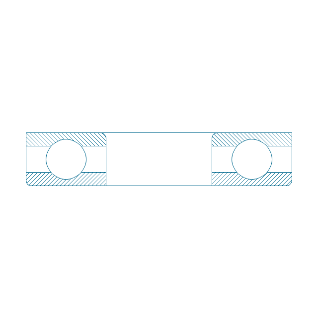
Deep groove ball bearing, hatched
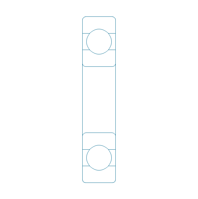
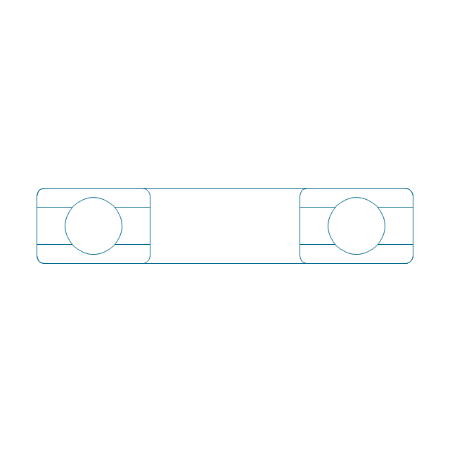
Deep groove ball bearing, unhatched
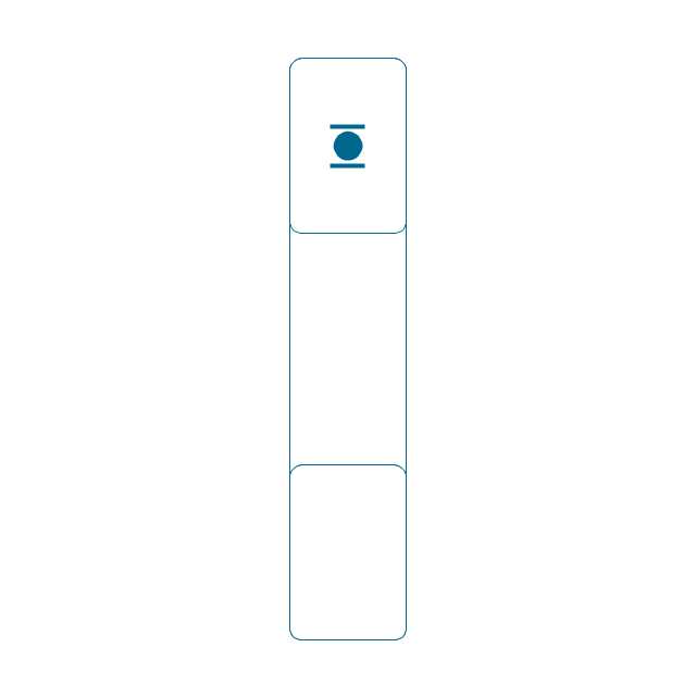
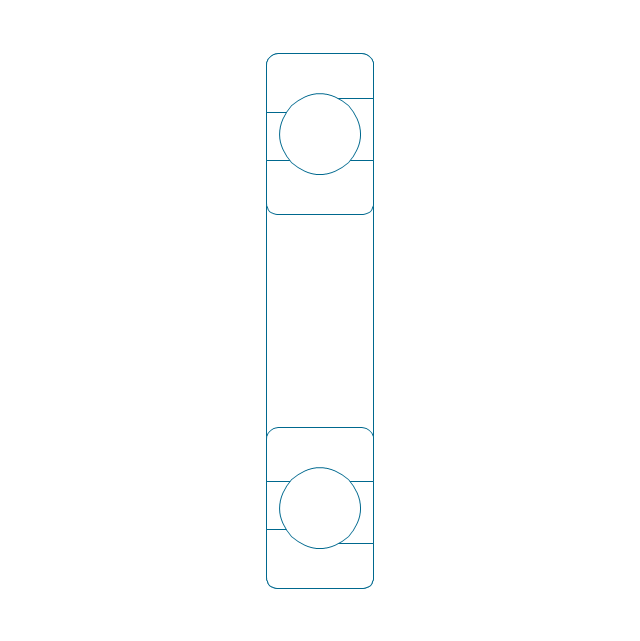
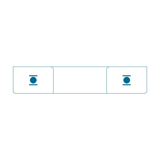
Deep groove ball bearing, simpl.
Angular contact ball bearing, simpl.
Angular contact ball bearing, unhatched
Angular contact ball bearing, hatched
Angular contact ball bearing dbl, unhatched
Angular contact ball bearing dbl, hatched
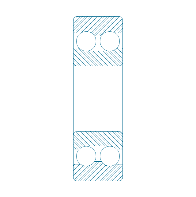
Self align. dbl ball bearing, hatched
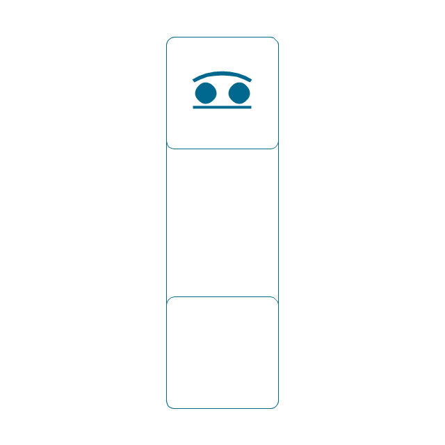
Self align. dbl bearing, simpl.
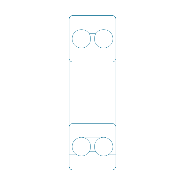
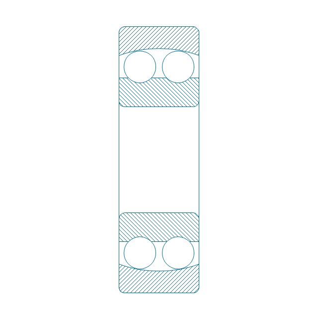
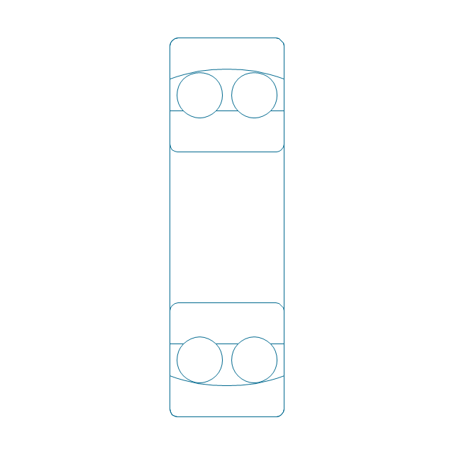
Self align. dbl ball bearing, unhatched
Thrust ball bearing, hatched
Thrust ball bearing, unhatched
Thrust ball bearing, simpl.
Thrust ball bearing, hatched 2
Thrust ball bearing, unhatched 2
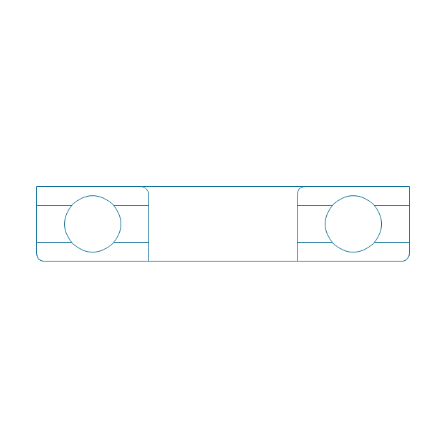
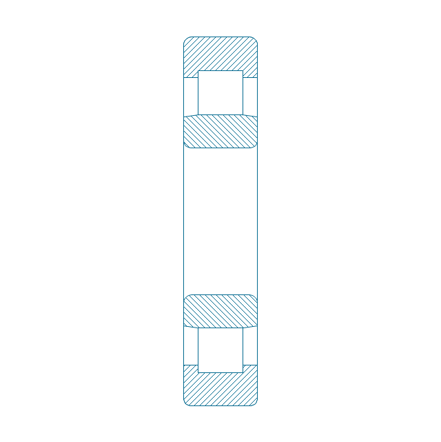
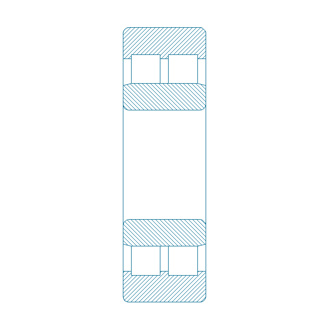
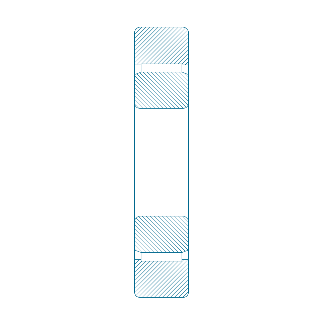
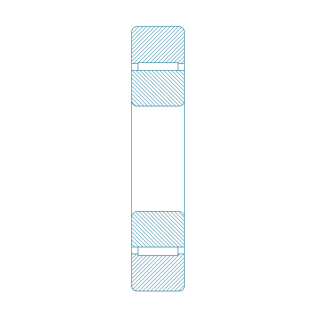
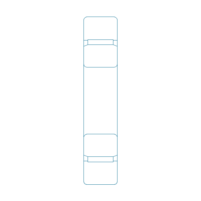
Cylindrical roller bearing, hatched
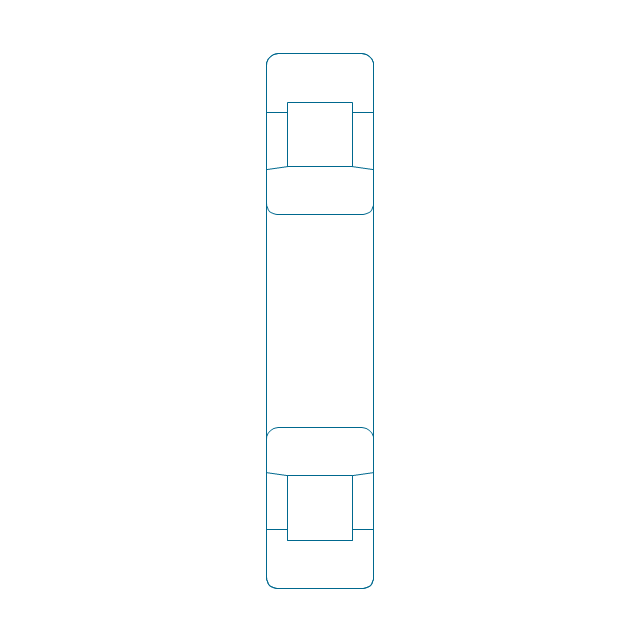
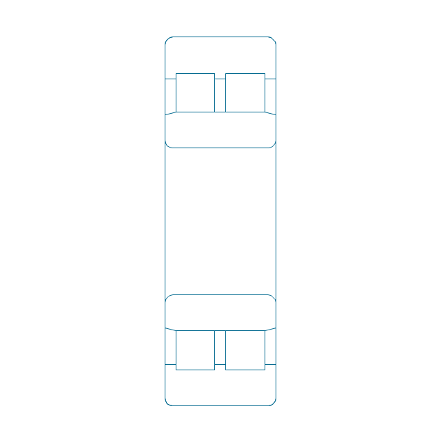
Cylindrical roller bearing, unhatched
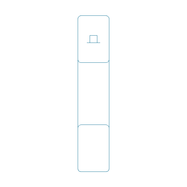
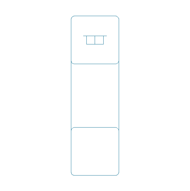
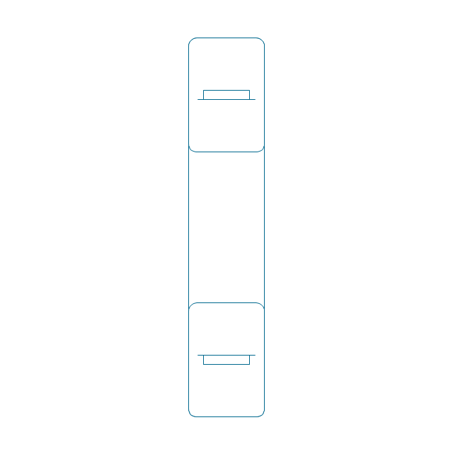
Cylindrical roller bearing, simpl.
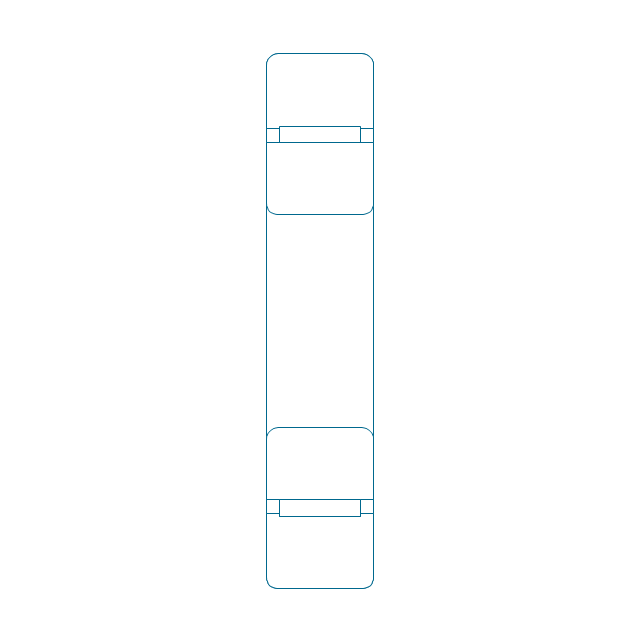
Cylindrical roller bearing dbl, simpl.
Cylindrical roller bearing dbl, unhatched
Cylindrical roller bearing dbl, hatched
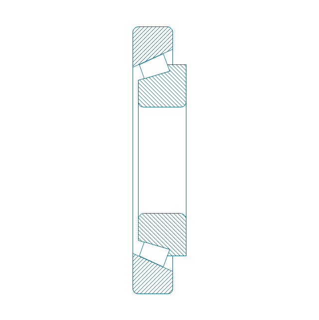
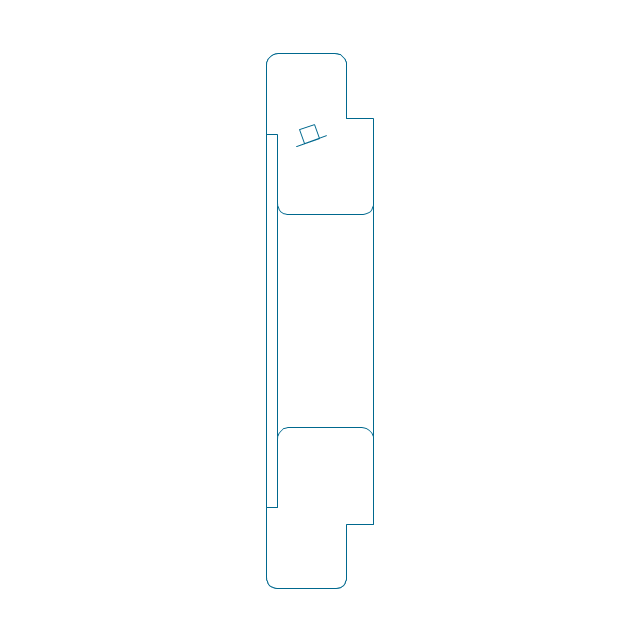
Taper roller bearing, hatched
Taper roller bearing, unhatched
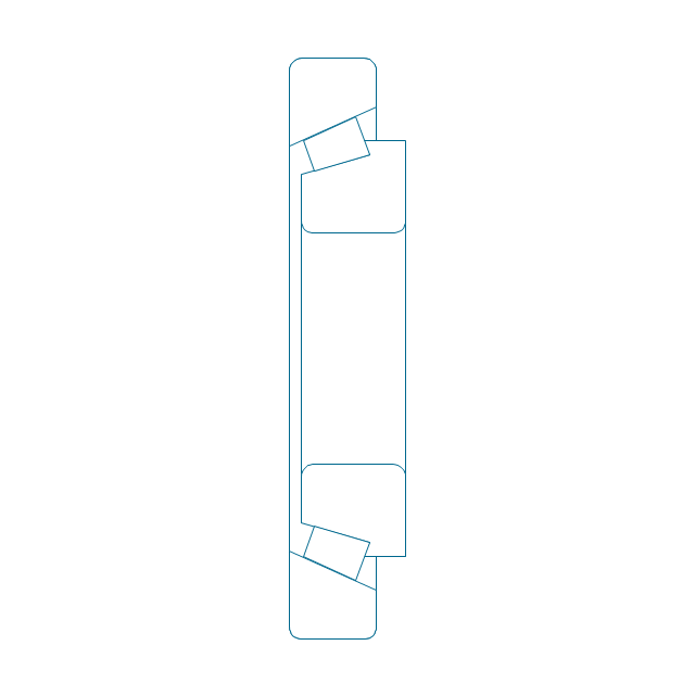
Taper roller bearing, simpl.
Needle roller bearing, hatched
Needle roller bearing, hatched 2
Needle roller bearing, unhatched
Needle roller bearing, unhatched 2
Needle roller bearing, simpl.
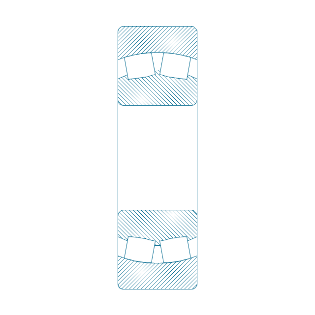
Spher. roller bearing dbl, hatched 2
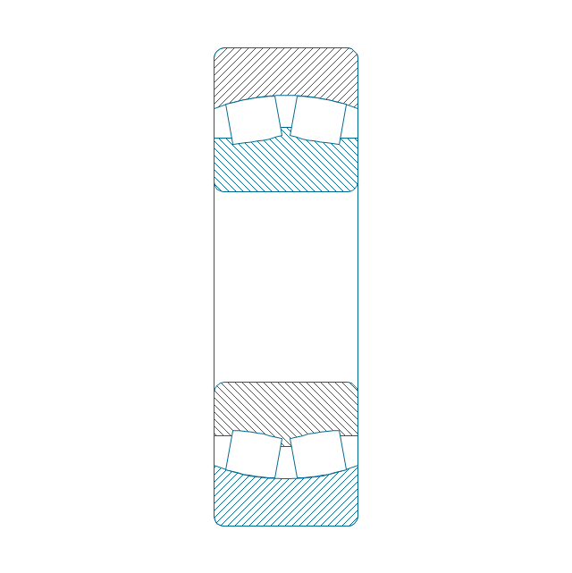
Spher. roller bearing dbl, hatched
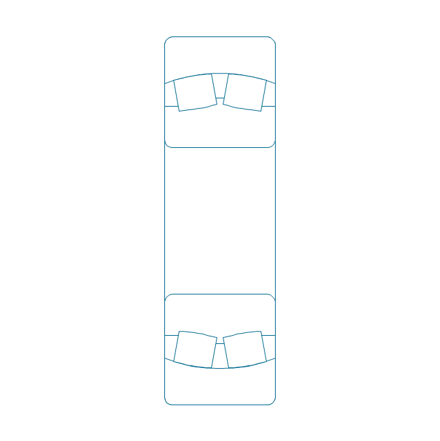
Spher. roller bearing dbl, unhatched
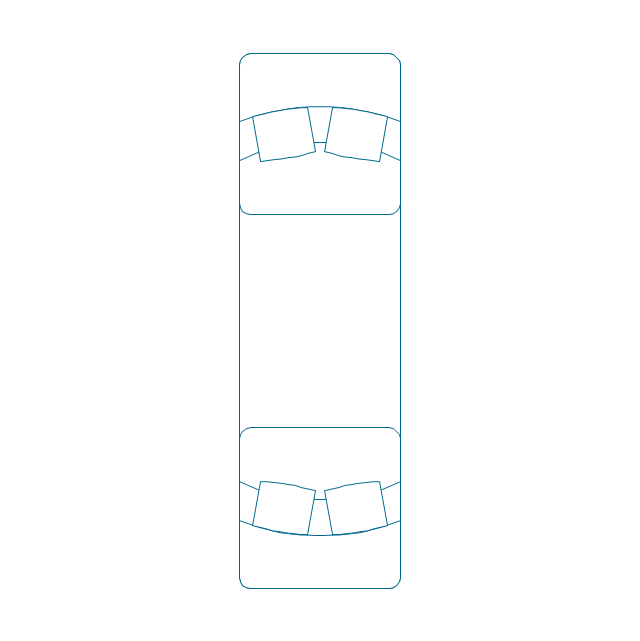
Spher. roller bearing dbl, unhatched 2
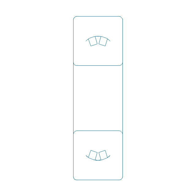
Spher. roller bearing dbl, simpl.
Gear
Gear (web)
-bearings---vector-stencils-library.png--diagram-flowchart-example.png)
Gear (keyway)
-bearings---vector-stencils-library.png--diagram-flowchart-example.png)
Gear (web, keyway)
-bearings---vector-stencils-library.png--diagram-flowchart-example.png)
Tapered shaft
Tapered key

Tapered key (gib head)
-bearings---vector-stencils-library.png--diagram-flowchart-example.png)
Tapered shaft

Hole chamfer
Shaft chamfer

Undercut
Centering bore
Cutaway

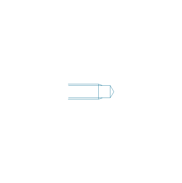
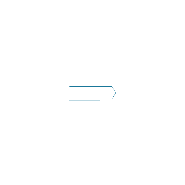
Spindle end

Spindle end (bore)
-bearings---vector-stencils-library.png--diagram-flowchart-example.png)
Countersunk hole

Countersunk hole 2

Threaded hole

Threaded hole 2

 Interactive Voice Response Diagrams
Interactive Voice Response Diagrams solution extends ConceptDraw DIAGRAM software with samples, templates and libraries of ready-to-use vector stencils that help create Interactive Voice Response (IVR) diagrams illustrating in details a work of interactive voice response system, the IVR system’s logical and physical structure, Voice-over-Internet Protocol (VoIP) diagrams, and Action VoIP diagrams with representing voice actions on them, to visualize how the computers interact with callers through voice recognition and dual-tone multi-frequency signaling (DTMF) keypad inputs.
Flow Chart Design - How to Design a Good Flowchart

- Mechanical Drawing Symbols | Technical Drawing Software ...
- Conventional Representation Of Ball Bearing And Roller Bearing
- Design elements - Bearings | Mechanical Engineering | Bearings ...
- Conventional Representation Of Building Materials
- Ppt Conventional Representation Of Bearings In Machine Drawing
- Design elements - Machines and equipment | Design elements ...
- Bearings - Vector stencils library | Conventional Representation Of ...
- Conventional Symbol Of Bearing In Mechanical Drawing
- Mechanical Drawing Symbols | Design elements - Bearings ...
- Mechanical Drawing Symbols | Mechanical Design Software ...
- Mechanical Drawing Symbols | Mechanical Design Software ...
- Mechanical Drawing Symbols | Technical Drawing Software | CAD ...
- Mechanical Drawing Symbols | Process Flowchart | Finite State ...
- Mechanical Drawing Software | Electrical Symbols — Qualifying ...
- Mechanical Engineering | Design elements - Bearings | Directional ...
- Mechanical Drawing Symbols | Design elements - Bearings ...
- Mechanical Drawing Symbols | Design elements - Bearings ...
- Conventional Signs And Symbols In Mechanical Engineering
- Mechanical Engineering Drawing Parts
- Technical drawing - Machine parts assembling | Mechanical ...