Seven Basic Tools of Quality — Quality Control
The seven basic tools of quality are basically a fixed set of graphical techniques used in troubleshooting related to quality to solve a majority of the quality-related issues and suitable for people with little formal training in statistics. They are cause-and-effect diagram (also known as the “Ishikawa” and the "fishbone" one), check sheet, control chart, histogram, Pareto chart, so called “scatter diagram” and “stratification” (also known to be “run chart” or “flow chart”).
The mentioned Seven Basic Tools stand can be compared to the more advanced statistical methods. Such methods are survey sampling, multivariate analysis, acceptance sampling, a design of experiments, statistical hypothesis testing as well as other methods developed within the field of “operations research”. The tools can be used as an example of a set of general ones used for controlling or planning project quality.
One of the most used types of diagrams mentioned before is so called “Ishikawa” diagram, also known as “fishbone one” or “herringbone diagram”. These diagrams can also be called as “cause-and-effect” ones as they are used for representing the cause and effect of some feature, which can influence on the final data. The check sheet (also sometimes called as “tally sheet”) is simply a form document used to collect data at a definite location (from where this data is generated) in a real time, while this data being captured is “qualitative” or “quantitative”. Another tool is “control chart”, also known as “Shewhart chart” or “process-behaviour” one. Such chart is used as a tool for controlling the statistical processes, determining whether a business (or manufacturing) process is under control at some definite time. The histogram is just a graphical representation of data, numerical one. “Pareto chart” was named after the “inventor” of so called “Pareto principle” and it used as a simple histogram for viewing causes of a problem from the largest number to the smallest one, being a statistical tool with help of which it is convenient to graphically demonstrate that mentioned “Pareto principle”.
Scatter diagram can also be known as a “scatter plot” (“scatter graph”, “scatter chart”, “scattergram”): this diagram is used for displaying different values for typically two variables of some data, usually having its points colour-coded. It is a type of plot or mathematical diagrams using so called “Cartesian coordinates” to display the needed values for a set of data that has to be illustrated. Once the points are colour-coded, then one additional variable can be displayed. The data can be displayed within a scatter diagrams only as a collection of points, each of which has its value determining the position on the horizontal axis. At the same time, the value of the other variable determining the position on the vertical axis on such type of diagram.
The last of the seven basic tools in quality control is a run chart, which is basically a form of line chart, also known as a “run-sequence plot”: it is a graph displaying the observed data in a series of time, representing some aspect of the output of a process of manufacturing or some other business process.
Using ConceptDraw DIAGRAM software and the Seven Basic Tools of Quality Solution can simplify your work of designing the needed diagram, including the mentioned ones, included in the quality control activity. Especially for ConceptDraw DIAGRAM users, there was a new application developed, known to be a “ConceptDraw STORE”. This new product of CS Odessa can be very useful for those who want to simply save their time and so their money by buying the needed solutions to use all the needed tools, such as stencil libraries with the design elements for creating the necessary diagrams, including the ones used as tools in quality control.
Thus, “Cause and Effect Diagram stencil library” from the “Seven Basic Tools of Quality” solution provides design elements for creating any needed “cause-and-effect”, or “fishbone” diagram. “Check Sheet” library includes colourful weekly check sheets. “Control Chart library” provides the examples of the control charts. “Histogram” one — histograms. “Pareto Chart library” shows the samples of Pareto Charts which all can be used as drafts for making the unique great looking as well as professionally looking charts. Process Flowchart Library allows all ConceptDraw DIAGRAM users to apply any needed design symbol to their drawings of Process Flowcharts for representing “Decision”, “Delay”, “Off-page reference”, “Document”, “Input-Output”, “Process Step”, “Alternate symbol for start or end points”, “Flown direction line”, etc. Run Chart, Scatterplot and Stratification Diagram libraries include the templates of the mentioned drawings that can be also used as examples as well as drafts.
Having ConceptDraw DIAGRAM software means enabling yourself to create a great looking “fishbone” diagram as well as a scatter one within only a couple of hours or even minutes, depending on how familiar you are both with ConceptDraw DIAGRAM diagramming and drawing software and its tools, such as solutions from ConceptDraw STORE. Thus, having the needed solution from the mentioned new application (ConceptDraw STORE), which all were developed for being used by all the ConceptDraw DIAGRAM users while working in ConceptDraw DIAGRAM software means being able to create the needed drawing looking simply smart and professional.

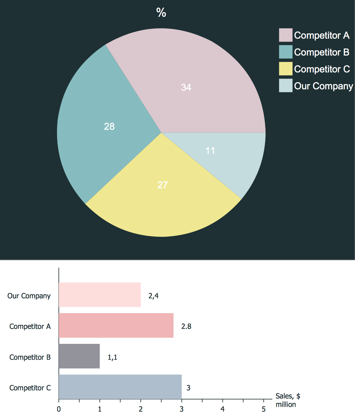
Example 1. Seven Basic Tools of Quality — Quality Control Chart
Seven Basic Tools of Quality Solution provides 9 libraries with 78 vector objects specially developed to help you realize quality control and easy design any type of diagram from the set of seven basic quality tools.


Seven Basic Tools of Quality Solution contains also large collection of predesigned examples and samples, all they are available for viewing and editing from ConceptDraw STORE.

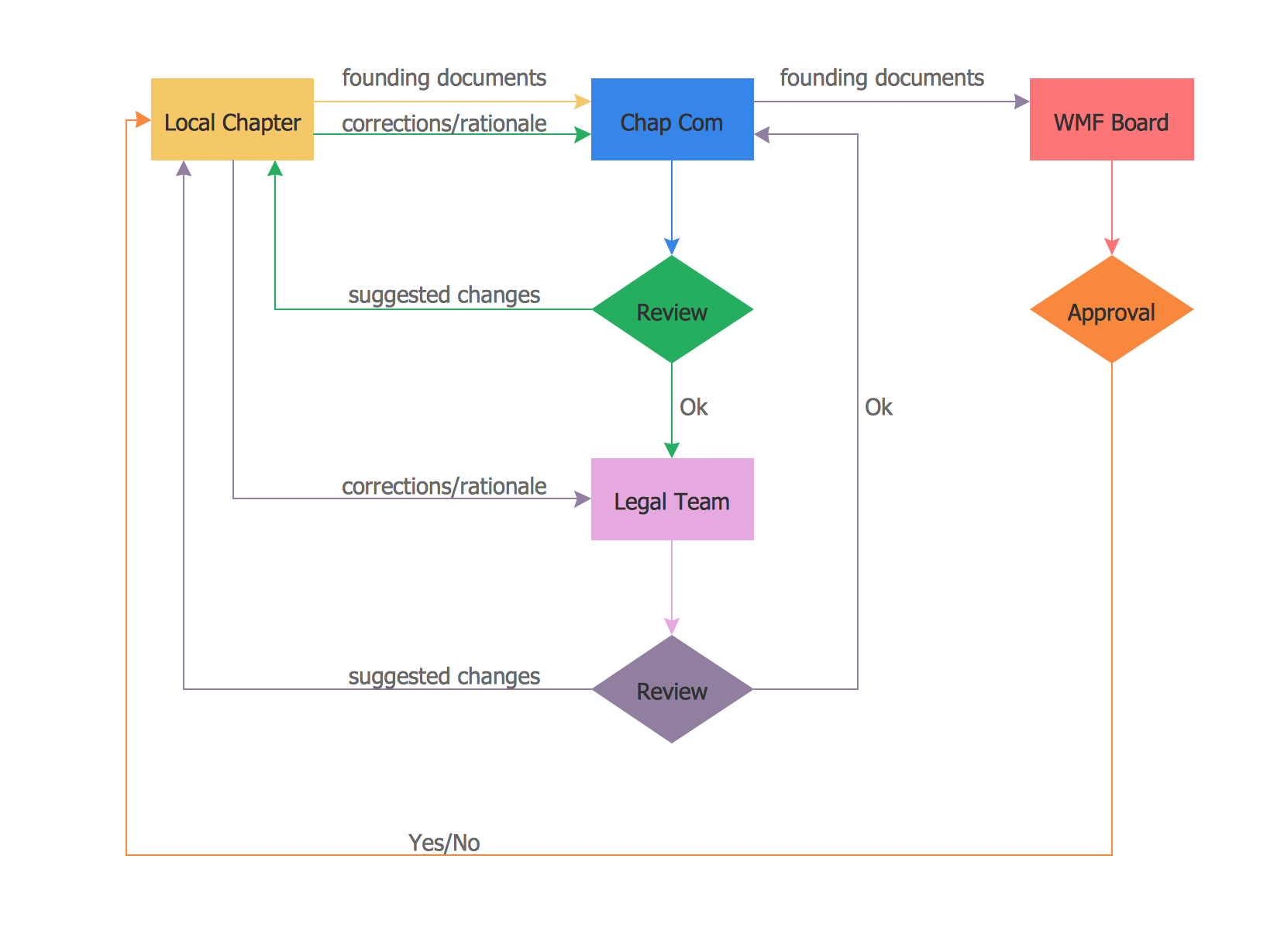
Example 2. Flowchart — QA Processes in HSRU
Providing the needed tools, such as pre-made samples of the described diagrams (as well as other diagrams, charts and flowcharts), stencil libraries with design symbols, developed for simplifying the work with creating charts, flowcharts, diagrams and maps, CS Odessa team tries to make it possible for all ConceptDraw DIAGRAM users to become specialists in drawing the schematics even if they have not as much experience in doing that. Trying the needed solution means almost ensuring yourself in being able to create professionally looking drawings any time you need them.