ConceptDraw Arrows10 Technology

Connection points are necessary for diagramming network, flowchart and organizational charts. In ConceptDraw you connect shapes by attaching, or snapping and gluing, connectors to shape connection points.
HelpDesk
How to Add, Move, or Delete Connection Points in ConceptDraw PRO on Mac

ConceptDraw Arrows10 Technology

How should diagramming software work? Is it possible to develop a diagram as quickly as the ideas come to you? The innovative Auto-connection mode is what you need to start draw.
How to Dramatically Reduce Drawing Time - New connection modes

While making the drawing process easier and faster.
This is more than enough versatility to draw any type of diagram with any degree of complexity.
ConceptDraw Arrows10 Technology

Using any other connection point provides a static connection, when you move connected objects the connector stays attached to the same point.
ConceptDraw Arrows10 Technology

"Tree"- mode drawing works like that. Just select objects in your drawing and press Tree or Chain button to connect all of them just in one click.
Your diagram looks professional and it took only a moment to draw.
S Video Connection

Standard Universal Audio & Video Connection Types

ConceptDraw Arrows10 Technology

You don't know how should diagramming software work?
Is it possible to develop a diagram as quickly as the ideas come to you?
Yes. The innovative ConceptDraw Arrows10 Technology - This is more than enough versatility to draw any type of diagram with any degree of complexity.
You can start draw your diagram manually now.
Double-headed Cross Functional Flowchart

Troubleshooting in Wireless Connection

Wireless Network Connection

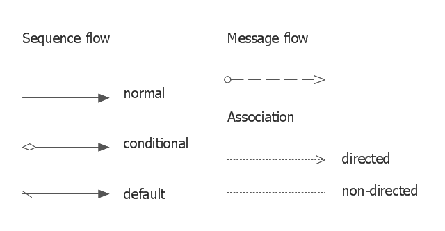
The vector stencils library "Connections BPMN1.2" contains 6 connection symbols of sequence flow, message flow, and association.
Use these shapes for drawing business process diagrams (BPMN 1.2) using the ConceptDraw PRO diagramming and vector drawing software.
"Connections.
Flow objects are connected to each other using Connecting objects, which are of three types: sequences, messages, and associations.
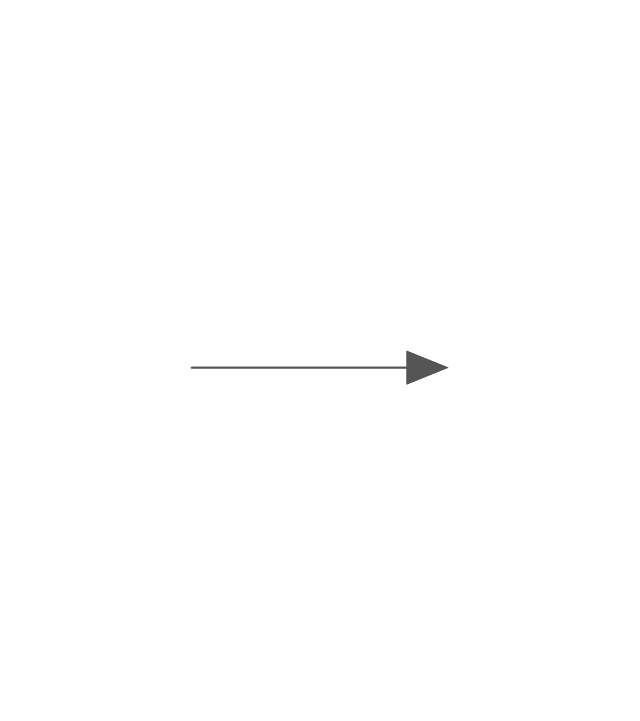
(1) Sequence Flow.
A Sequence Flow is represented with a solid line and arrowhead, and shows in which order the activities are performed. The sequence flow may also have a symbol at its start, a small diamond indicates one of a number of conditional flows from an activity, while a diagonal slash indicates the default flow from a decision or activity with conditional flows.
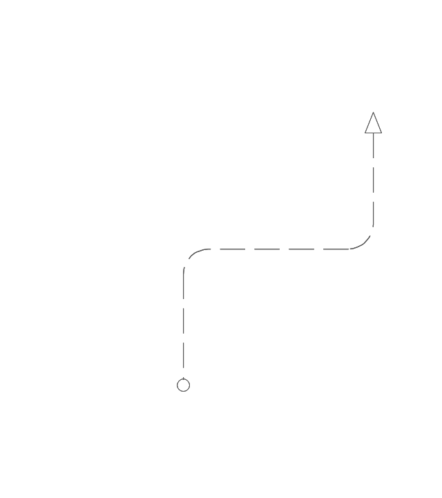
(2) Message Flow.
A Message Flow is represented with a dashed line, an open circle at the start, and an open arrowhead at the end. It tells us what messages flow across organizational boundaries (i.e., between pools). A message flow can never be used to connect activities or events within the same pool.
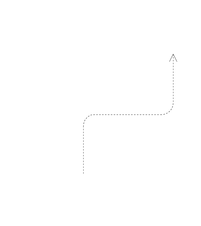
(3) Association.
An Association is represented with a dotted line. It is used to associate an Artifact or text to a Flow Object, and can indicate some directionality using an open arrowhead (toward the artifact to represent a result, from the artifact to represent an input, and both to indicate it is read and updated). No directionality is used when the Artifact or text is associated with a sequence or message flow (as that flow already shows the direction)." [Business Process Model and Notation. Wikipedia]
The example "Design elements - Connections BPMN1.2" is included in the Business Process Diagram solution from the Business Processes area of ConceptDraw Solution Park.
Use these shapes for drawing business process diagrams (BPMN 1.2) using the ConceptDraw PRO diagramming and vector drawing software.
"Connections.
Flow objects are connected to each other using Connecting objects, which are of three types: sequences, messages, and associations.
(1) Sequence Flow.
A Sequence Flow is represented with a solid line and arrowhead, and shows in which order the activities are performed. The sequence flow may also have a symbol at its start, a small diamond indicates one of a number of conditional flows from an activity, while a diagonal slash indicates the default flow from a decision or activity with conditional flows.
(2) Message Flow.
A Message Flow is represented with a dashed line, an open circle at the start, and an open arrowhead at the end. It tells us what messages flow across organizational boundaries (i.e., between pools). A message flow can never be used to connect activities or events within the same pool.
(3) Association.
An Association is represented with a dotted line. It is used to associate an Artifact or text to a Flow Object, and can indicate some directionality using an open arrowhead (toward the artifact to represent a result, from the artifact to represent an input, and both to indicate it is read and updated). No directionality is used when the Artifact or text is associated with a sequence or message flow (as that flow already shows the direction)." [Business Process Model and Notation. Wikipedia]
The example "Design elements - Connections BPMN1.2" is included in the Business Process Diagram solution from the Business Processes area of ConceptDraw Solution Park.
BPMN1.2 connection symbols
How To Create Professional Diagrams

Use templates, samples and special libraries for your needs.
Cross-functional flowchart Templates portrait, metric

- Cross-Functional Horizontal
- Cross-Functional Vertical
- Opportunity Flowchart
- Swim Lane Map
ConceptDraw Arrows10 Technology

Add text to connectors the same way you add text to any object - doubleclick a connector and type.
ConceptDraw Arrows10 Technology

You don't have to think about your connectors, they think for you.
Diagram Software - The Best Choice for Diagramming

The vector stencils library "Connection BPMN 1.2" contains 6 connection symbols of sequence flow, message flow, and association.
Use these shapes for drawing business process diagrams (BPMN 1.2) in the ConceptDraw PRO diagramming and vector drawing software extended with the Business Process Diagram solution from the Business Processes area of ConceptDraw Solution Park.
www.conceptdraw.com/ solution-park/ business-process-diagram
Sequence Flow
Message Flow

Association

Association
Message Flow
Sequence Flow
Use Case Diagrams technology with ConceptDraw PRO

- Wired Connection Diagram
- Troubleshooting in Wireless Connection | Using Both Wired and ...
- Network Diagram Software Logical Network Diagram | Wireless ...
- Troubleshooting in Wireless Connection | PM Response | Computer ...
- Mobile satellite communication network diagram | Using Both Wired ...
- Standard Universal Audio & Video Connection Types | Audio Visual ...
- ConceptDraw Arrows10 Technology | How to Dramatically Reduce ...
- S Video Connection | Audio and Video Connectors | Design ...
- Audio and Video Interfaces and Connectors | Standard Universal ...
- Audio & Video Connector Types | Standard Universal Audio & Video ...
- Local Area Network Diagram
- Standard Universal Audio & Video Connection Types | How To Print ...
- Design elements - Audio and video connectors | S Video Connection
- Design elements - Audio and video connectors | S Video Connection
- Standard Universal Audio & Video Connection Types | Audio and ...
- Wireless Networks | Visio Exchange | Cisco Network Diagrams ...
- Audio & Video Connector Types | Audio & Video Connections ...
- Using Both Wired and Wireless Connections | Wireless access point ...
- Draw Diagram Connection To Pc
- Connection BPMN 1.2 - Vector stencils library