Diagramming Software for Design UML Activity Diagrams


UML Class Diagram Example - Medical Shop

UML Class Diagram Example for Transport System

How To Create a Workflow Diagram

UML 2 4 Process Flow Diagram

UML Use Case Diagram Example - Taxi Service

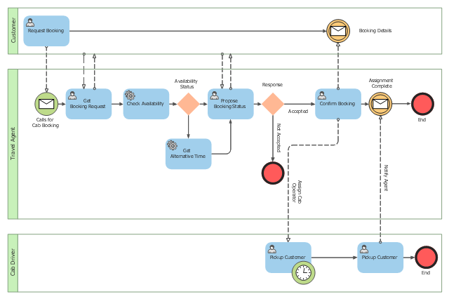
This BPMN (Business Process Model and Notation) collaboration diagram sample depicts interactions between customer, travel agent and cab driver, which are defined as a sequence of activities, and represent the message exchange during a cab booking process.
"Business process modeling is used to communicate a wide variety of information to a wide variety of audiences. BPMN is designed to cover this wide range of usage and allows modeling of end-to-end business processes to allow the viewer of the Diagram to be able to easily differentiate between sections of a BPMN Diagram. There are three basic types of sub-models within an end-to-end BPMN model: Private (internal) business processes, Abstract (public) processes, and Collaboration (global) processes...
Collaboration (global) processes.
A collaboration process depicts the interactions between two or more business entities. These interactions are defined as a sequence of activities that represent the message exchange patterns between the entities involved. Collaboration processes may be contained within a Pool and the different participant business interactions are shown as Lanes within the Pool. In this situation, each Lane would represent two participants and a direction of travel between them. They may also be shown as two or more Abstract Processes interacting through Message Flow. These processes can be modeled separately or within a larger BPMN Diagram to show the Associations between the collaboration process activities and other entities. If the collaboration process is in the same Diagram as one of its corresponding private business process, then the activities that are common to both processes can be associated." [Business Process Model and Notation. Wikipedia]
The business process modeling diagram example "Cab booking public process - Collaboration BPMN 2.0 diagram" was designed using the ConceptDraw PRO diagramming and vector drawing software extended with the Business Process Diagram solution from the Business Processes area of ConceptDraw Solution Park.
Business process modeling
UML Class Diagram. Design Elements

UML Class Diagram Example - Buildings and Rooms

UML Use Case Diagram Example. Registration System

UML Use Case Diagram Example. Registration System
Financial Trade UML Use Case Diagram Example

How to Help Customers be More Productive

UML Composite Structure Diagram

UML Software

 Business Diagrams
The Business Diagrams Solution extends ConceptDraw DIAGRAM with an extensive collection of professionally designed illustrative samples and a wide variety of vector stencils libraries, which are the real help for all business-related people, business analysts, business managers, business advisers, marketing experts, PR managers, knowledge workers, scientists, and other stakeholders allowing them to design the bright, neat, expressive and attractive Bubble Diagrams, Circle-Spoke Diagrams, Circular Arrows Diagrams, and Venn Diagrams with different quantity of sets in just minutes; and then successfully use them in documents, reports, statistical summaries, and presentations of any style.
Object-Oriented Development (OOD) Method
 Method *")
 Business Process Workflow Diagrams
The Business Process Workflow Diagrams solution enhances the ConceptDraw DIAGRAM functionality with predesigned examples, samples and a numerous collection of predesigned vector objects of workflow chart elements, icons, arrows, connectors, and varied wor
BPMN 2.0

- Automated payroll management system UML activity diagram | UML ...
- Activity Diagram For Tourism Management System
- Sequence Diagram Of Tourism Management
- Use Case Diagram For Tourism Management System
- Hotel Management System Activity Diagram
- Sequence Diagram Hd Images Of Tourism Management System
- Activity Diagram Using Swimlane For Hotel Management System
- Sequence Diagram For Transport Management System
- How To Create a Workflow Diagram | UML Use Case Diagram ...
- Data Flow Diagram Of Travel Management System
- Activity Diagram For Hotel Management System Pdf
- Activity Diagram For Pharmacy Management System
- Cab booking public process - Collaboration BPMN 2.0 diagram ...
- UML Class Diagram Notation
- Actitvity Diagram For Taxi Management System
- Process Flowchart | Data Flow Diagrams (DFD) | IDEF0 Diagrams ...
- Payroll Hotel Management System Flowchart
- Financial Trade UML Use Case Diagram Example | UML Use Case ...
- Activity Diagram For Event Management System
- Er Diagram For Tour Management