The vector stencils library "Cisco network topology" contains 89 symbols of Cisco network devices and design elements for drawing computer network topology diagrams using the ConceptDraw PRO diagramming and vector drawing software.
"Network topology is an arrangement of the various elements (links, nodes, etc.) of a computer network. Essentially, it is the topological structure of a network, and may be depicted physically or logically. Physical topology refers to the placement of the network's various components, including device location and cable installation, while logical topology shows how data flows within a network, regardless of its physical design. Distances between nodes, physical interconnections, transmission rates, and/ or signal types may differ between two networks, yet their topologies may be identical.
A good example is a local area network (LAN): Any given node in the LAN has one or more physical links to other devices in the network; graphically mapping these links results in a geometric shape that can be used to describe the physical topology of the network. Conversely, mapping the data flow between the components determines the logical topology of the network." [Network topology. Wikipedia]
The example "Design elements - Cisco network topology" is included in the Cisco Network Diagrams solution from the Computer and Networks area of ConceptDraw Solution Park.
Cisco network topology symbols

Cisco Network Topology. Cisco icons, shapes, stencils and symbols

Sales Process Flowcharts

 Cisco Network Diagrams
Cisco Network Diagrams solution extends ConceptDraw DIAGRAM with the best characteristics of network diagramming software. Included samples, templates and libraries of built-in standardized vector Cisco network icons and Cisco symbols of computers, network devices, network appliances and other Cisco network equipment will help network engineers, network designers, network and system administrators, as well as other IT professionals and corporate IT departments to diagram efficiently the network infrastructure, to visualize computer networks topologies, to design Cisco computer networks, and to create professional-looking Cisco Computer network diagrams, Cisco network designs and schematics, Network maps, and Network topology diagrams in minutes.
The vector stencils library "Cisco switches and hubs" contains 26 symbols of Cisco switches and hubs for drawing computer network diagrams.
"A switch is a device used on a computer network to physically connect devices together. Multiple cables can be connected to a switch to enable networked devices to communicate with each other. Switches manage the flow of data across a network by only transmitting a received message to the device for which the message was intended. Each networked device connected to a switch can be identified using a MAC address, allowing the switch to regulate the flow of traffic. This maximises security and efficiency of the network. Because of these features, a switch is often considered more "intelligent" than a network hub. Hubs neither provide security, or identification of connected devices. This means that messages have to be transmitted out of every port of the hub, greatly degrading the efficiency of the network." [Network switch. Wikipedia]
"An Ethernet hub, active hub, network hub, repeater hub, multiport repeater or hub is a device for connecting multiple Ethernet devices together and making them act as a single network segment. It has multiple input/ output (I/ O) ports, in which a signal introduced at the input of any port appears at the output of every port except the original incoming. A hub works at the physical layer (layer 1) of the OSI model. The device is a form of multiport repeater. Repeater hubs also participate in collision detection, forwarding a jam signal to all ports if it detects a collision." [Ethernet hub. Wikipedia]
The symbols example "Cisco switches and hubs - Vector stencils library" was created using the ConceptDraw PRO diagramming and vector drawing software extended with the Cisco Network Diagrams solution from the Computer and Networks area of ConceptDraw Solution Park.
www.conceptdraw.com/ solution-park/ computer-networks-cisco
Cisco hub

100BaseT hub

Small hub

Workgroup switch

Workgroup switch, subdued

Voice-enabled workgroup switch

ATM switch

LAN2LAN switch

ISDN switch

MGX 8000 multiservice switch

Multilayer switch with Si

Multilayer switch

Multilayer switch with Si, subdued

Program switch

Data center switch

Voice-enabled ATM switch

IP DSL switch

Content switch

Content service switch 1100

Virtual layer switch

Layer 2 remote switch

Server switch

Multilayer remote switch

Multifabric server switch

Access gateway

Long-Reach CPE

Hotel Service Process
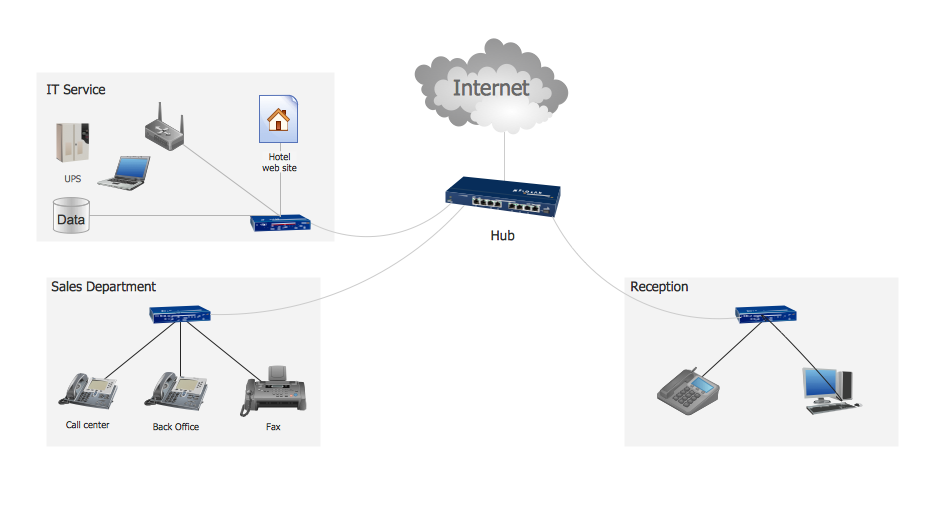
Hotel Network Topology Diagram


Rack Diagrams
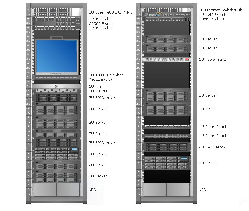

Design Element: Rack Diagram for Network Diagrams
.png)
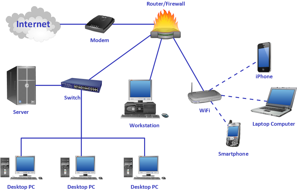
Network Diagram Software Backbone Network

Cisco Optical. Cisco icons, shapes, stencils and symbols

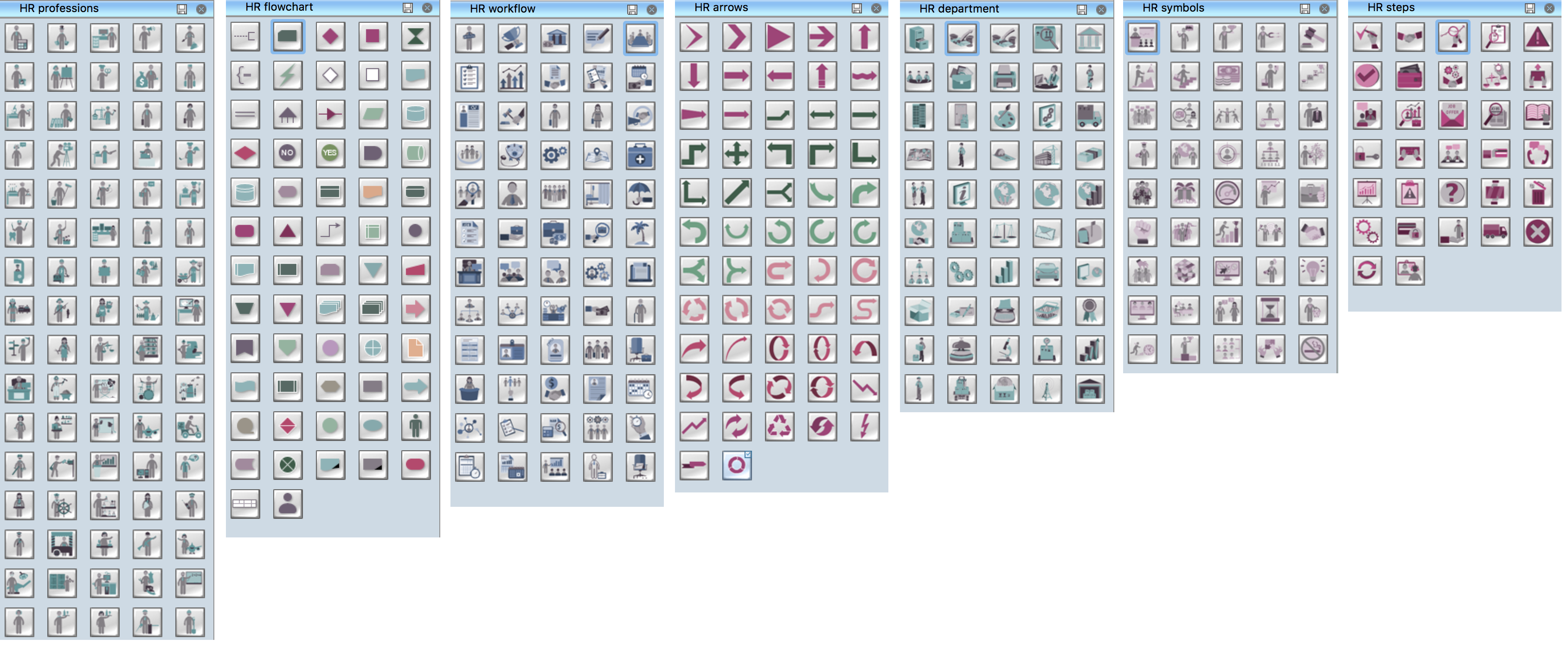
HR Flowchart Symbols
HelpDesk
How to Create a Data Flow Diagram

Crea Diagramas De Flujo
ConceptDraw Arrows10 Technology

- Cisco Network Diagrams | Data Flow Diagrams (DFD) | Active ...
- ATM UML Diagrams | Data Flow Diagrams | Cisco Network ...
- Data Flow Diagrams (DFD) | Cisco Network Diagrams | Cafe and ...
- Data Flow Diagrams (DFD) | ATM UML Diagrams | Cisco Network ...
- Cisco Network Diagrams | Data Flow Diagrams (DFD) | Cross ...
- Data Flow Diagrams (DFD) | Cafe and Restaurant Floor Plans ...
- Cisco Network Diagrams | Scheduler agent supervisor pattern | Data ...
- Bbs Data Flow Diagram
- Data Flow Diagrams (DFD) | Process Flowchart | Cisco Network ...
- Data Flow Diagrams (DFD) | ConceptDraw Solution Park ...
- Basic Flowchart Symbols and Meaning | Cisco Products Additional ...
- How to Create Cisco Network Diagram Using ConceptDraw ...
- UML Deployment Diagram Example - ATM System UML diagrams ...
- Data Flow Symbols Shapes Stencils And Icons
- Data Flow Diagrams (DFD) | Process Flowchart | UML Use Case ...
- Logical network topology diagram | Network Diagram Software ...
- Cisco Network Diagrams | Telecommunication Network Diagrams ...
- Cisco Network Diagrams | Cisco Network Design. Cisco icons ...
- Windows Azure | Cisco WAN. Cisco icons, shapes, stencils and ...
- Hotel Network Topology Diagram | How to Create a Data Flow ...