 Business Processes Area
Solutions of Business Processes area extend ConceptDraw PRO software with samples, templates and vector stencils libraries for drawing business process diagrams and flowcharts for business process management.
Business Process Flowchart Symbols

Process Flowchart


Business Process Modeling Software for Mac

 Cross-Functional Flowcharts
Cross-functional flowcharts are powerful and useful tool for visualizing and analyzing complex business processes which requires involvement of multiple people, teams or even departments. They let clearly represent a sequence of the process steps, the order of operations, relationships between processes and responsible functional units (such as departments or positions).
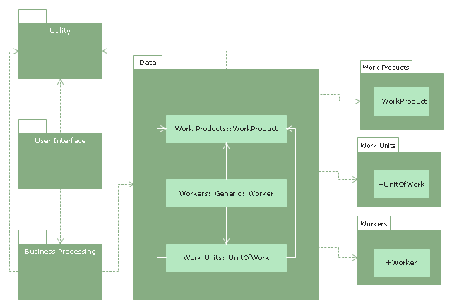
"Business process modeling (BPM) in systems engineering is the activity of representing processes of an enterprise, so that the current process may be analyzed and improved. BPM is typically performed by business analysts and managers who are seeking to improve process efficiency and quality. The process improvements identified by BPM may or may not require information technology involvement, although that is a common driver for the need to model a business process, by creating a process master. Business process modeling results in the improvement of the way tasks performed by the business. They can pick up errors or cons about the way processes are currently being performed and model an improved way of carrying out these processes." [Business process modeling. Wikipedia]
The UML package diagram example "Business process" was created using the ConceptDraw PRO diagramming and vector drawing software extended with the Rapid UML solution from the Software Development area of ConceptDraw Solution Park.
The UML package diagram example "Business process" was created using the ConceptDraw PRO diagramming and vector drawing software extended with the Rapid UML solution from the Software Development area of ConceptDraw Solution Park.
UML package diagram
BPM Software

Basic Flowchart Symbols and Meaning


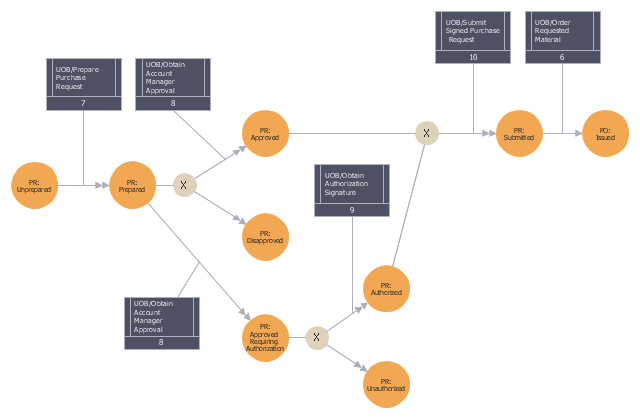
This IDEF3 diagram example was redesigned from the Wikimedia Commons file: 5-21 Completed Transition Schematic.jpg.
[commons.wikimedia.org/ wiki/ File:5-21_ Completed_ Transition_ Schematic.jpg]
"As with the Process Schematic, the correctness of the Object Schematic and
associated elaborations are confirmed through validation with the domain expert. After reviewing the Transition Schematic, the domain expert observes that the allowable state transitions displayed in the schematic do not include those representative of a failed request. ...
The domain expert also identified transitions through which the identity of the object was preserved and transitions where the object was actually transformed into an entirely different object. The domain expert’s comments to the analyst yield the schematic
depicted in Figure 5-21." [IDEF3 Process Description Capture Method Report AL-TR-1995-XXXX. idef.com/ pdf/ Idef3_ fn.pdf]
The sample "Completed transition schematic - IDEF3 diagram" was created using the ConceptDraw PRO diagramming and vector drawing software extended with the solution "IDEF Business Process Diagrams" from the area "Business Processes" of ConceptDraw Solution Park.
IDEF3 business process diagram
Influence Diagram

- Process Flowchart | Cross-Functional Flowcharts | The Best Tool for ...
- Process Flowchart | Business Processes Area | Cross-Functional ...
- Business Processes
- Business Process Modeling Software for Mac | Business Process ...
- Process Flowchart | How to Add a Business Process Diagram to a ...
- | BPMN 2.0 | How to Create a BPMN Diagram Using Border Events ...
- Business Process Modeling Notation Template | Business process ...
- Process Flowchart | Business process model diagram BPMN 1.2 ...
- Business Process Modeling Notation Template | Business Process ...
- Business Process Modeling Software for Mac | BPM Software ...
- Business Process Modeling Software for Mac | Business process ...
- Work Order Process Flowchart. Business Process Mapping Examples
- Visio Business Process Modeling Examples
- How To Create a MS Visio Business Process Diagram Using ...
- Business process diagram BPMN 1.2 - Hiring process | BPMN 2.0 ...
- Example Of Business Sales Analyst With Result And Diagram
- Business Process Modeling Notation Template | Business Process ...
- Business process diagram BPMN 1.2 - Hiring process | Cab booking ...
- UML Business Process | Business Process Modeling with ...