CAD Drawing Software for Making Mechanic Diagram and Electrical Diagram Architectural Designs


Technical Drawing Software

Mechanical Drawing Symbols

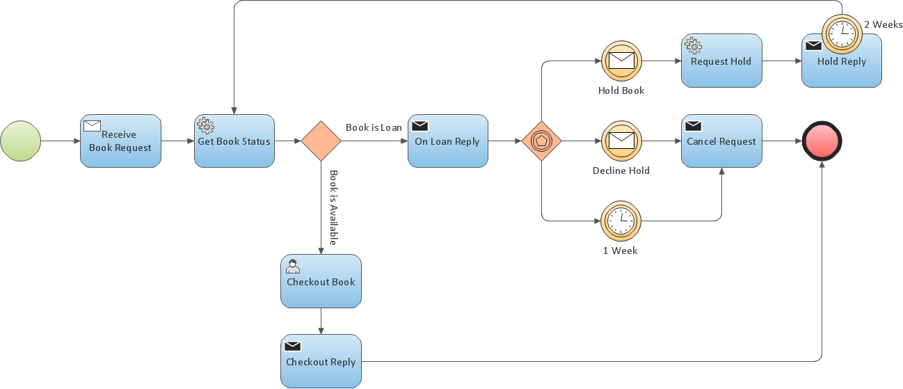
How to Draw Business Process Diagrams with RapidDraw Interface
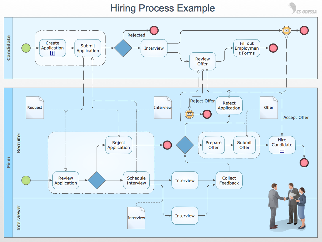
Business Process Modeling Resume
Flowchart Marketing Process. Flowchart Examples

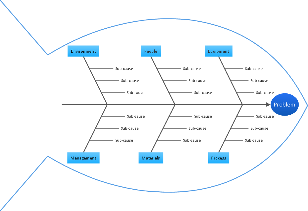
TQM Diagram Tool
Fire Evacuation Plan Template

Pyramid Diagram and Pyramid Chart

Circuits and Logic Diagram Software

Decision Making
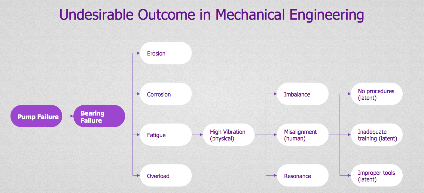

Root Cause Tree Diagram

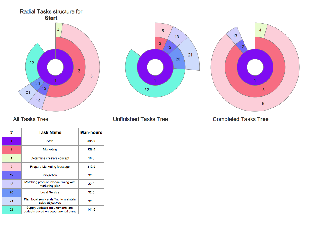
Project — Working With Tasks
- Technical Drawing Software | How to Create a Mechanical Diagram ...
- Sphere Symbol In Engg Drawing
- Technical drawing - Machine parts assembling | Mechanical ...
- Mechanical Drawing Symbols | Process Flowchart | Accounting ...
- Technical Drawing Software | Process Flowchart | Electrical Symbols ...
- Mechanical Drawing Symbols | Process Flowchart | Accounting ...
- Mechanical Drawing Symbols | Mechanical Engineering | Process ...
- Mechanical Drawing Symbols | Process Flowchart | Mechanical ...
- Mechanical Drawing Symbols | Elements location of a welding ...
- Mechanical Drawing Symbols | Mechanical Engineering ...
- Mechanical Drawing Symbols | Technical Drawing Software ...
- Mechanical Drawing Symbols | Mechanical Engineering | Technical ...
- Mechanical Drawing Symbols | Mechanical Engineering | Elements ...
- Machenical Engineering Parts With Drawing
- Technical Drawing Software | Mechanical Engineering | How to ...
- Mechanical Drawing Symbols | Mechanical Engineering | Design ...
- Mechanical Drawing Symbols | Elements location of a welding ...
- Mechanical Drawing Symbols | Elements location of a welding ...
- Mechanical Drawing Symbols | Elements location of a welding ...
- Mechanical Drawing Symbols | Mechanical Engineering ...