Electrical Symbols, Electrical Diagram Symbols

 Network Layout Floor Plans
Network Layout Floor Plans solution extends ConceptDraw DIAGRAM software functionality with powerful tools for quick and efficient documentation the network equipment and displaying its location on the professionally designed Network Layout Floor Plans. Never before creation of Network Layout Floor Plans, Network Communication Plans, Network Topologies Plans and Network Topology Maps was not so easy, convenient and fast as with predesigned templates, samples, examples and comprehensive set of vector design elements included to the Network Layout Floor Plans solution. All listed types of plans will be a good support for the future correct cabling and installation of network equipment.
Electrical Symbols — Switches and Relays

Star Network Topology


Mesh Network Topology Diagram

Process Flow Maps

 HVAC Plans
Use HVAC Plans solution to create professional, clear and vivid HVAC-systems design plans, which represent effectively your HVAC marketing plan ideas, develop plans for modern ventilation units, central air heaters, to display the refrigeration systems for automated buildings control, environmental control, and energy systems.
Types of Flowcharts


Process Flowchart


 Computer Network Diagrams
Computer Network Diagrams solution extends ConceptDraw DIAGRAM software with samples, templates and libraries of vector icons and objects of computer network devices and network components to help you create professional-looking Computer Network Diagrams, to plan simple home networks and complex computer network configurations for large buildings, to represent their schemes in a comprehensible graphical view, to document computer networks configurations, to depict the interactions between network's components, the used protocols and topologies, to represent physical and logical network structures, to compare visually different topologies and to depict their combinations, to represent in details the network structure with help of schemes, to study and analyze the network configurations, to communicate effectively to engineers, stakeholders and end-users, to track network working and troubleshoot, if necessary.
 Business Diagrams
The Business Diagrams Solution extends ConceptDraw DIAGRAM with an extensive collection of professionally designed illustrative samples and a wide variety of vector stencils libraries, which are the real help for all business-related people, business analysts, business managers, business advisers, marketing experts, PR managers, knowledge workers, scientists, and other stakeholders allowing them to design the bright, neat, expressive and attractive Bubble Diagrams, Circle-Spoke Diagrams, Circular Arrows Diagrams, and Venn Diagrams with different quantity of sets in just minutes; and then successfully use them in documents, reports, statistical summaries, and presentations of any style.
 Stakeholder Onion Diagrams
The Stakeholder Onion Diagram is often used as a way to view the relationships of stakeholders to a project goal. A basic Onion Diagram contains a rich information. It shows significance of stakeholders that will have has influence to the success achieve
 Target and Circular Diagrams
This solution extends ConceptDraw DIAGRAM software with samples, templates and library of design elements for drawing the Target and Circular Diagrams.
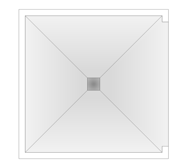
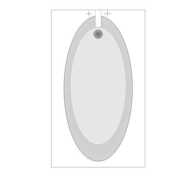
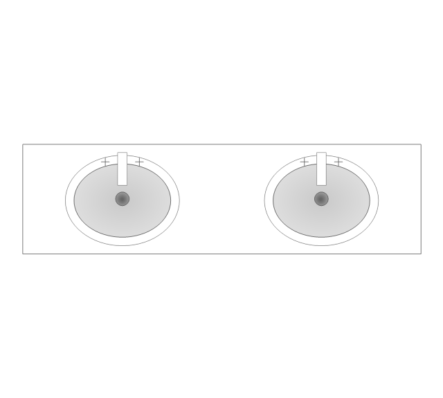
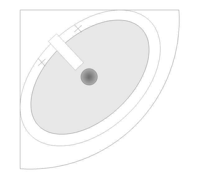
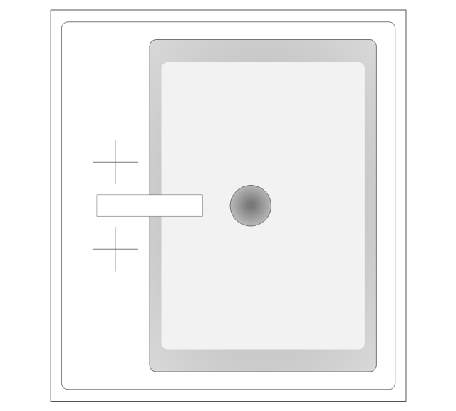
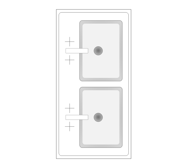
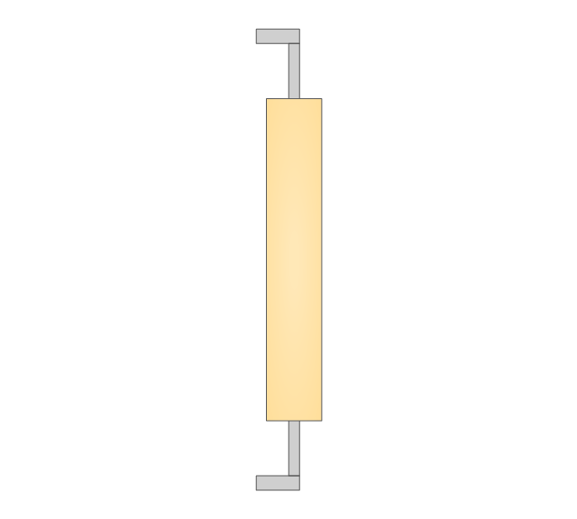
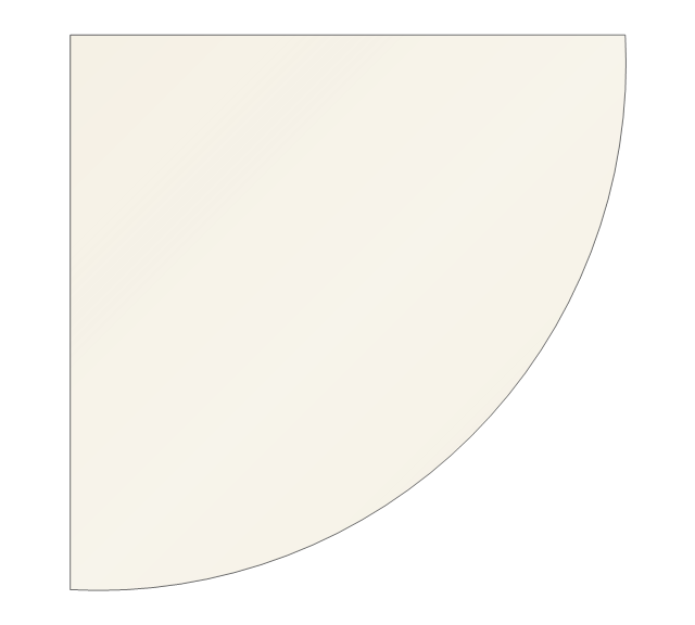
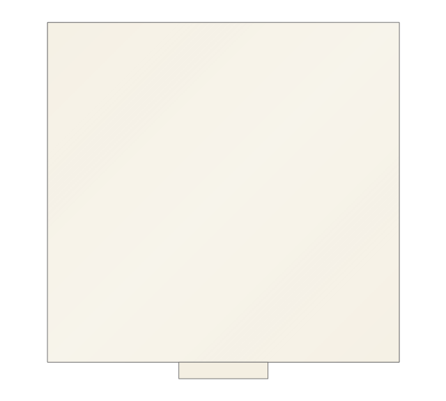
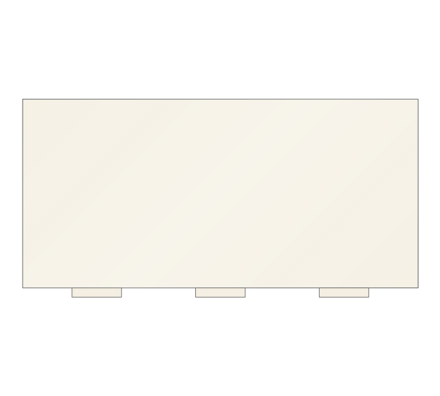
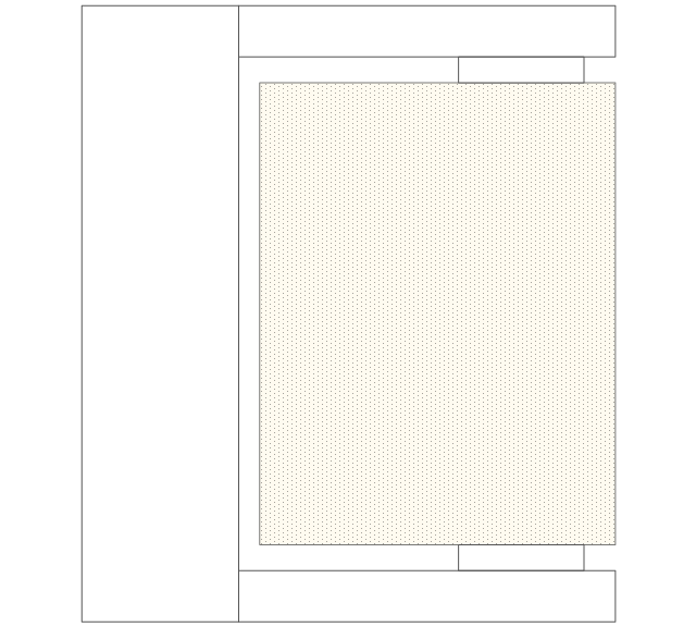
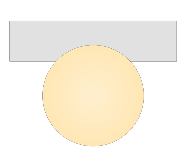
The vector stencils library "Bathroom" contains 41 bathroom equipment shapes. Use it for drawing bathroom layout plans: bathtubs, toilets, faucets, sinks, showers, bathroom furniture the ConceptDraw PRO diagramming and vector drawing software extended with the Floor Plans solution from the Building Plans area of ConceptDraw Solution Park.
Shower
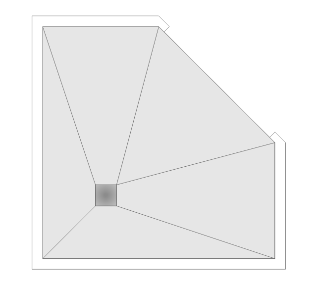
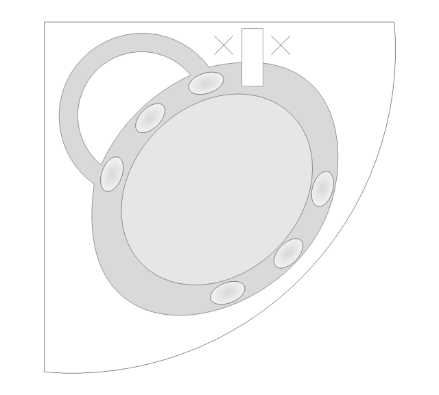
Corner Shower
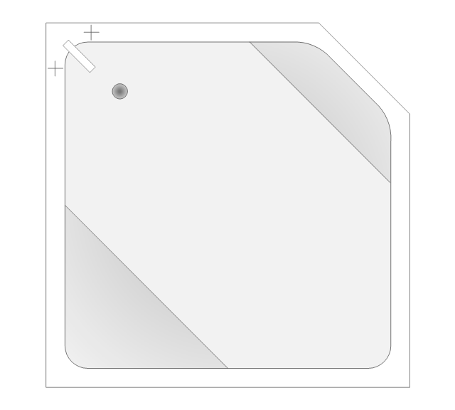
Corner Bath
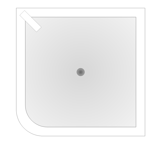
Square Tub
Bath Tub
Bath 1
Bath 2

Spa Tub
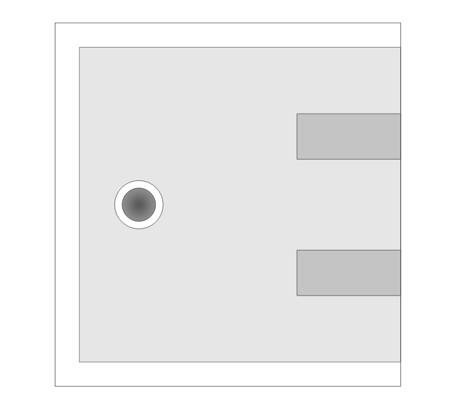
Bidet
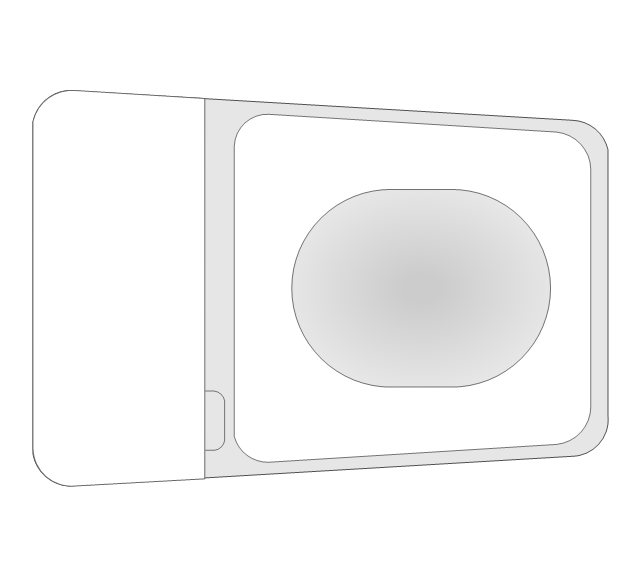
Wall Toilet
Toilet 1
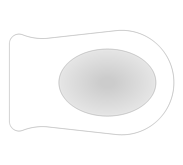
Toilet 2

Toilet 3
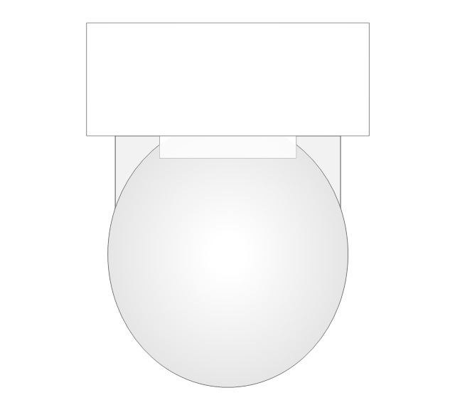
Squat WC
Pedestal Sink 1 (Oval)
-bathroom---vector-stencils-library.png--diagram-flowchart-example.png)
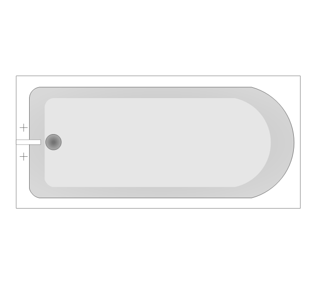
Pedestal Sink 2 (Oval)
-bathroom---vector-stencils-library.png--diagram-flowchart-example.png)
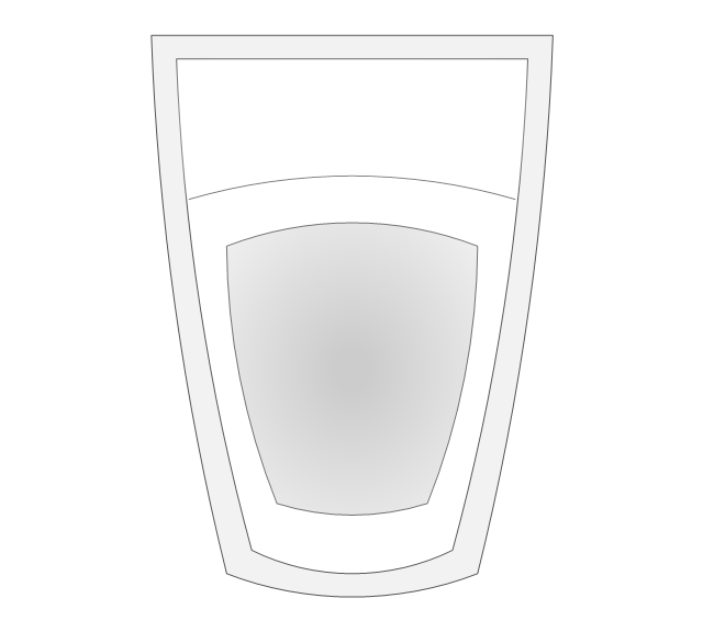
Pedestal Sink 3

Pedestal Sink 4
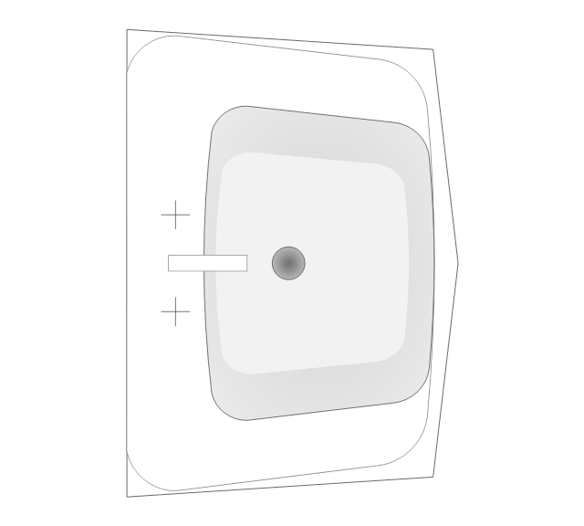
Countertop Sink

Round Sink

Vanity Sink

Double Vanity Sinks
Corner Sink
Basin
Double Basin
Towel Rack

Towel Rack with Towel
Toilet Paper Holder
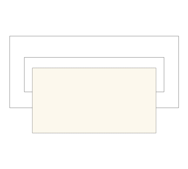
Countertop

Corner Counter
Cabinet 1
Cabinet 2

Cabinet 3
Medicine Cabinet 1

Medicine Cabinet 2

TP Dispenser
Hamper

Single Light
Double Light
3 Light Bar

4 Light Bar
Types of Flowchart - Overview

This PFD sample was redesigned from the Wikipedia file: NaturalGasCondensate.png.
"This is a schematic flow diagram of a typical facility for separating and recovering liquid condensate from raw natural gas."
[en.wikipedia.org/ wiki/ File:NaturalGasCondensate.png]
"Natural-gas condensate is a low-density mixture of hydrocarbon liquids that are present as gaseous components in the raw natural gas produced from many natural gas fields. It condenses out of the raw gas if the temperature is reduced to below the hydrocarbon dew point temperature of the raw gas.
The natural gas condensate is also referred to as simply condensate, or gas condensate, or sometimes natural gasoline because it contains hydrocarbons within the gasoline boiling range. Raw natural gas may come from any one of three types of gas wells:
(1) Crude oil wells - Raw natural gas that comes from crude oil wells is called associated gas. This gas can exist separate from the crude oil in the underground formation, or dissolved in the crude oil.
(2) Dry gas wells - These wells typically produce only raw natural gas that does not contain any hydrocarbon liquids. Such gas is called non-associated gas.
(3) Condensate wells - These wells produce raw natural gas along with natural gas liquid. Such gas is also non-associated gas and often referred to as wet gas." [Natural-gas condensate. Wikipedia]
The process flow diagram example "Natural gas condensate - PFD" was drawn using the ConceptDraw PRO software extended with the Chemical and Process Engineering solution from the Chemical and Process Engineering area of ConceptDraw Solution Park.
Process flow diagram (PFD)
-natural-gas-condensate---pfd.png--diagram-flowchart-example.png)
- Shipping, receiving and storage | Warehouse layout floor plan ...
- Plant Layout Plans | Design elements - Workflow diagram ...
- Design elements - Buildings and green spaces | Emergency Plan ...
- Fire Evacuation Plan Template
- Local area network (LAN). Computer and Network Examples | Hotel ...
- How to Draw a Chemical Process Flow Diagram | Chemical and ...
- Plant Layout Plans | Flow chart Example. Warehouse Flowchart ...
- Drawing Illustration | Draw Flowcharts with ConceptDraw | Beautiful ...
- Sport Field Plans
- Crude oil distillation unit - PFD | Process Flow Diagram Symbols ...
- Packaging, loading, customs - Vector stencils library | Manufacturing ...
- Interior Design . Storage and Distribution — Design Elements ...
- Process Flow Diagram Symbols | How to Create a Mechanical ...
- Baseball Diagram – Colored Baseball Field | Baseball Field Sample ...
- Network Layout Floor Plans | Electrical Symbols, Electrical Diagram ...
- Warehouse with conveyor system - Floor plan | Conceptual diagram ...
- Interior Design . Storage and Distribution — Design Elements ...
- Stencil Factory
- Forklift Drawing
- Interior Design . Storage and Distribution — Design Elements ...