Network Diagrams are an important tool which gives you a clear picture of your network topology connections and processes. It often helps you see the drawbacks in your infrastructure and realize how you can fix it. If you have accurate schema of your network and its connections at hand, you are ready to find a quick solution when the issues come up.
Network Topology in communication networks helps understand how the network is arranged, with all its nodes and connecting lines. The network geometry can be described via the physical topology or the logical topology.
ConceptDraw DIAGRAM diagramming and vector drawing software extended with Computer Network Diagrams Solution from the Computer and Networks Area offers extensive drawing tools which make it a powerful Network Topology Mapper.
Computer Network Diagrams Solution offers a variety of predesigned templates and samples and 8 libraries with numerous ready-to-use vector objects, which will help create network topology diagrams of any complexity in minutes.
How To Create Network Topology Diagram
ConceptDraw can be used both for business diagrams and drawing and for creating network diagrams. The detailed menu and icon layout make the tool easy to use. Its Drag-n-Drop functionality requires very little training to learn the basics of its software and use it regularly. You can now create custom objects or shapes and save them in the Library for future usage.
Launch ConceptDraw DIAGRAM
Set a page orientation: File – Page Setup – Horizontal Orientation – Ok.
In the Computer Network Diagrams Solution open the libraries containing the necessary shapes:
Computer network
Network hardware
At the Network hardware library drag a NETGEAR Fast Ethernet hub object.Rename it “Hub”.
Holding down the Option key (ALT), copy the object. Place the copies on the page.
Drag a Workstation object from the Computer network library.
Holding down the Option key (ALT), copy the object. Place the copies on the page.
Use Direct Connector from the Toolbar.
Open Inspectors – Line tab. Set the endpoints.
Choose the connector’s color.
Connect all the objects on the page in a required direction.
From the File menu open the Document Properties – Page Size – Adjust to Drawing Contents – Ok.
Using Cmd+A, select all the objects.
Open Inspectors – Text tab. Select the font and the Text size. Change the Text color.
Using the yellow diamond around the text box, move it to the right place.
Save your document via the File menu – Save or Save As.
Choose Export in the File menu to export your document to different formats.
You can import/export Visio files and change them according to your needs.
Your drawing is ready!
The ConceptDraw DIAGRAM offers over 70 templates and thousands of shapes, including IT focused elements that represent Network Security, Azure Architecture, AWS Architecture, Cloud Computing, Cisco Network, Wireless Networks, Vehicular Networking, Telecommunication Network, Active Directory components, as well as detailed network components and network appliances and routes.
Video. How To Create Network Topology Diagram (1min 04sec)
The following features make ConceptDraw DIAGRAM the best Network Topology Mapper:
You don't need to be an artist to draw professional looking diagrams in a few minutes.
Large quantity of ready-to-use vector objects makes your drawing diagrams quick and easy.
Great number of predesigned templates and samples give you the good start for your own diagrams.
ConceptDraw DIAGRAM provides you the possibility to use the grid, rules and guides. You can easily rotate, group, align, arrange the objects, use different fonts and colors to make your diagram exceptionally looking.
All ConceptDraw DIAGRAM documents are vector graphic files and are available for reviewing, modifying, and converting to a variety of formats: image, HTML, PDF file, MS PowerPoint Presentation, Adobe Flash, MS Visio.
Using ConceptDraw STORE you can navigate through ConceptDraw Solution Park, managing downloads and updates. You can access libraries, templates and samples directly from the ConceptDraw STORE.
If you have any questions, our free of charge support is always ready to come to your aid.
Every corporate network is unique, though there are guidelines and best practices in developing networks. As it is quite difficult to implement a pure topology within a company, using a hybrid network topology is considered a better solution. As a rule, such network assembles advantages and features of source topologies.
This diagram is an example of the Hybrid network. This type of network topology means a conjunction of other network topologies. Such as star-bus, ring-mesh topologies, etc. It should be obviously diverse networks. The final computer network inherits both advantages and disadvantages of its ingredients. Using the ConceptDraw Computer and Networks solution including vector graphic libraries and templates one can develop professional custom network diagrams of any topology and complexity.
When studying a business process or system involving the transfer of data, it is common to use a Data Flow Diagram (DFD) to visualize how data are processed. Being initially used exclusively in regards to the flow of data through a computer system, now DFDs are employed as the business modeling tools. They are applied to describe the business events and interactions, or physical systems involving data storage and transfer. ConceptDraw DIAGRAM is a powerful Data Flow Diagram software thanks to the Data Flow Diagrams solution from the Software Development area of ConceptDraw Solution Park.
UML Component Diagram Online Shopping. This sample was created in ConceptDraw DIAGRAM diagramming and vector drawing software using the UML Component Diagram library of the Rapid UML Solution from the Software Development area of ConceptDraw Solution Park.
This sample shows the concept of the online shopping and is used for the understanding of the online shopping processes, of the online shops working processes, for projection and creating of the online stores.
Picture: UML Component Diagram Example - Online Shopping
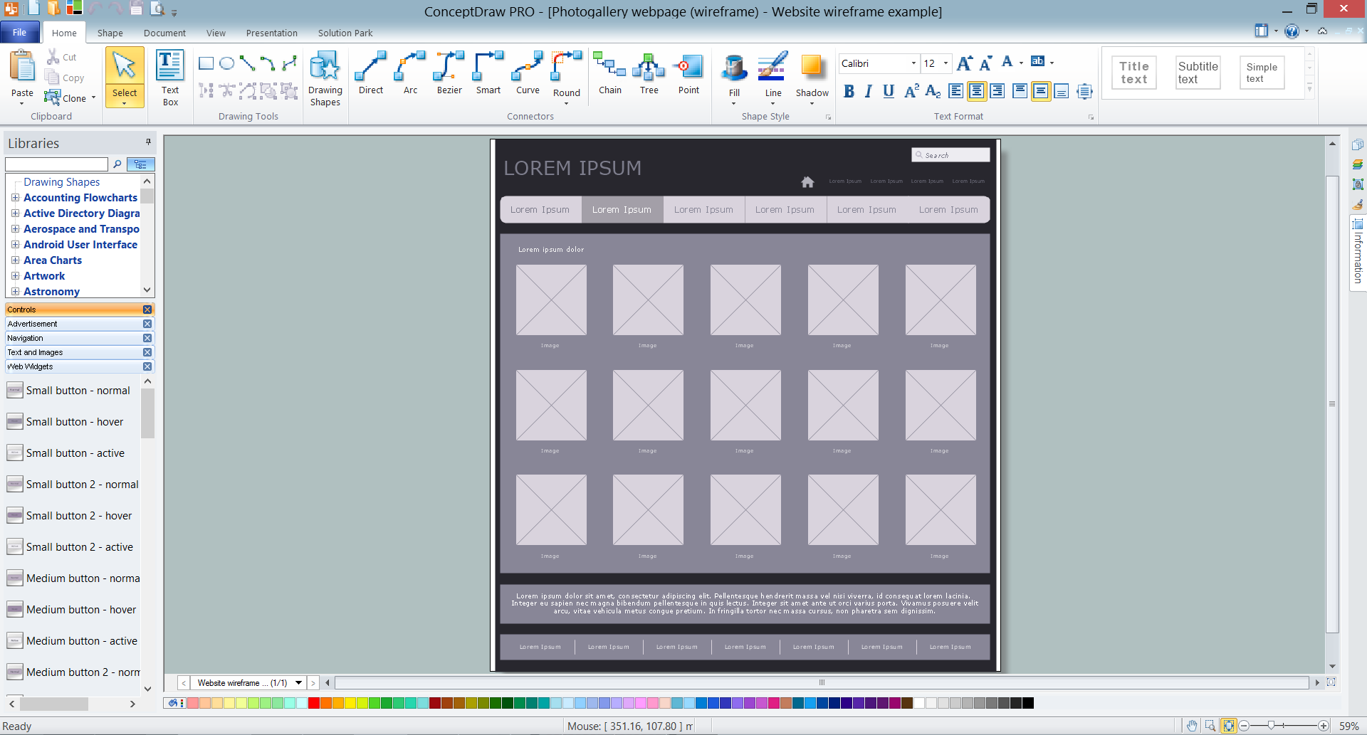
A wireframe is a scheme of a future web page. Wireframe illustrates the web page structure, location and size of the main elements, as well as their interaction with the user. With such scheme designer defines the functionality of the page, not its appearance.
Installing a wireless network is not very different from a regular network. After you configure the interfaces, the half of network configuration is done. You should also set routing, masquerading and set all the addresses.
This Interactive Voice Response Diagram (IVR) diagram depicts topology of an IVR system and shows physical and logical structure of an IVR system. It is created using facilities of the ConceptDraw solutions: Computer and Networks Diagrams in conjunction with Interactive Voice Response Diagrams. The diagram helps to understand how the call-center's equipment interacts with customer's calls to route them in the proper manner enabling client to get a useful response.
Computer networks nowadays are spread all across the world. The large number of parameters, such as geographic scale or communication protocols, can divide networks. One of the most common types of networks is called local area network (LAN). It convenient to represent network examples by means of diagrams.
This local area network (LAN) diagram provides an easy way to see the way the devices in a local network are interacted. The diagram uses a library containing specific symbols to represent network equipment , media and the end-user devices such as computers (PC, mac, laptop) , network printer, hubs, server and finally a modem. There are two types of network topologies: physical and logical. The current diagram represents precisely a physical type of LAN topology because it refers to the physical layout of a local network equipment.
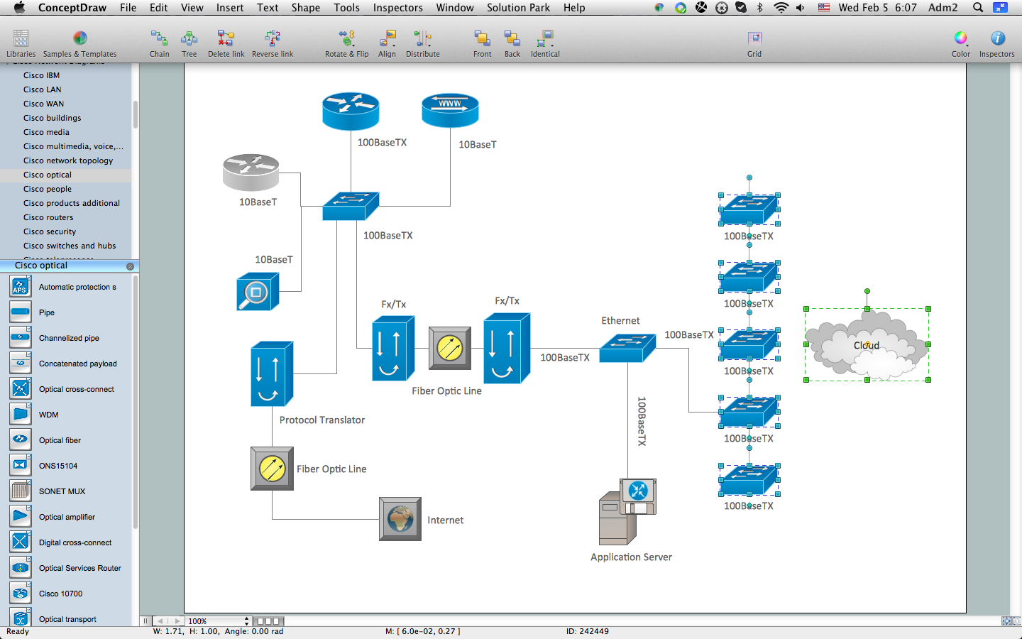
The Cisco Network Diagrams Solution from the Computer and Networks area of ConceptDraw Solution Park helps you to create the Cisco Network Diagrams quick and easy using the ConceptDraw DIAGRAM diagramming and vector drawing software.
The Cisco Network Diagrams Solution contains 14 libraries with 450 ready-to-use predesigned vector objects.
Using diagrams, you can visualize the flow of the information or build a detailed data structure. There's no need to have a degree in software and database design with ConceptDraw DIAGRAM , because this software has all the tools needed in developing models and diagrams. Project planning, designing and prototyping was never so easy.
This UML diagrams can be used to visualize a model of the data base development process. A UML diagram shows a graphical view of a structure of software system: components and relationships.
Using Unified Modeling Language helps to depict logical and physical elements of a data base, visually represent requirements and sub-systems. UML diagrams allows developers to organize and predict critical issues, as well as collaborate data base information.
Picture: Software and Database Design with ConceptDraw DIAGRAM


 Your drawing is ready!