Concept Map
Thinking about creating a concept map you can consider deploying such useful and professional tool as ConceptDraw DIAGRAM diagramming and drawing software for a reason of it being one of the best drawing applications for making the mentioned drawings. To make any needed concept map it is necessary to know what it means. Any of the concept maps can be also sometimes called as a “conceptual diagram”, being simply a diagram which the help of which it is convenient to depict the suggested relationships between a few different concepts. Being popular as well as a commonly used graphical tool, the concept map is known to be widely used among the technical writers, software engineers, instructional designers and many other specialists, users of ConceptDraw DIAGRAM
One of the reasons why it is always better to use ConceptDraw DIAGRAM drawing application is that it is always simpler to make the mentioned concept maps using it, especially if you have Concept Maps Solution downloaded from ConceptDraw STORE – another product of CS Odessa, full of the solutions which are all available for all ConceptDraw DIAGRAM users to get.
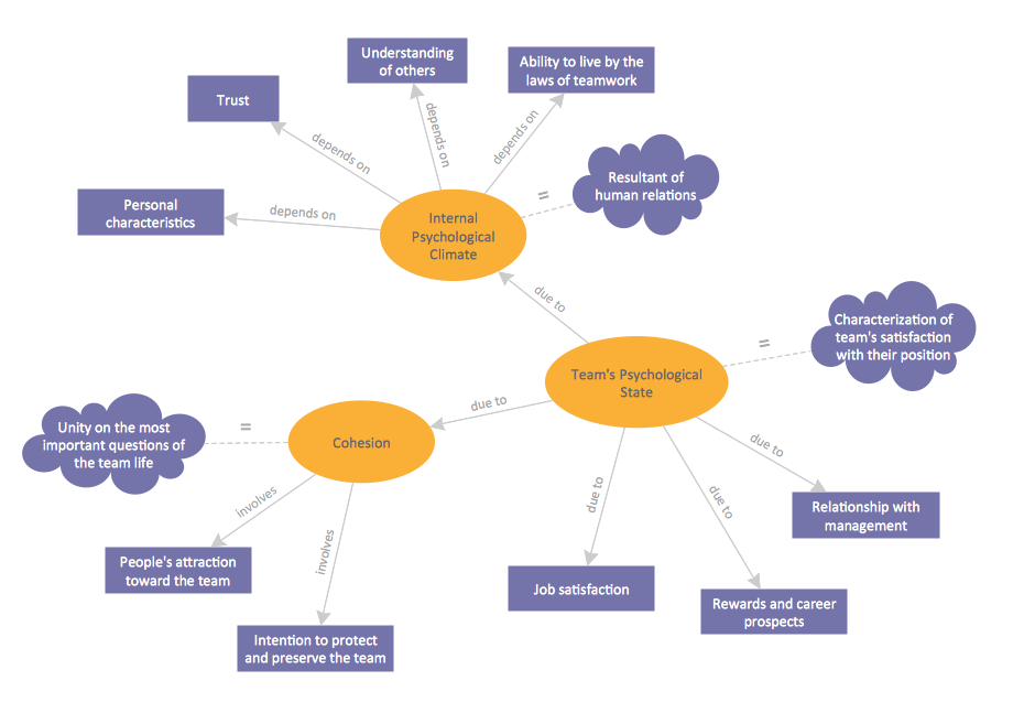
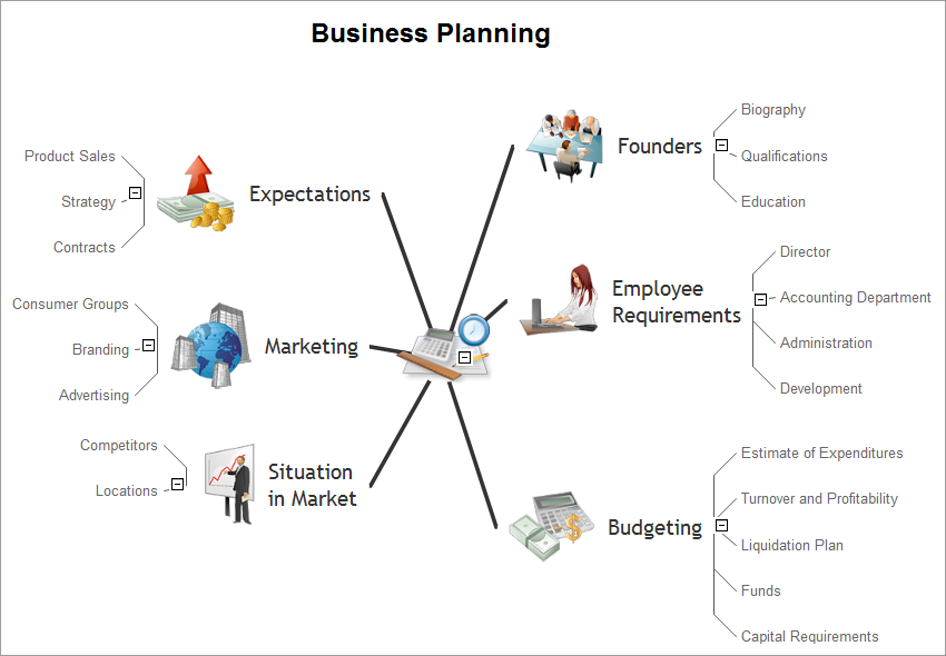
Example 1. Concept Map — Team Psychological Characteristics
To enable yourself to organize and to structure some knowledge in a form of a concept map, you can represent any data, which can always be illustrated in a better way than text – in a visual way by making a diagram, map, charts or plan. With the aid of concept map it becomes much simpler to understand the entities as well as the relationships between them and the connections between their different parts.
Any concept map is known to be representing the ideas and some particular information in a way of drawing the boxes or circles to help illustrate the existing data visually. Every content map is known to be having the mentioned boxes or circles connected with the labelled arrows in a hierarchical structure. The relationships between different concepts may be always articulated in any needed linking phrases.
One of the existing and commonly used techniques to visualize such relationships between different concepts is known to be a process of concept mapping. The mentioned process is widely used for defining the ontology of the systems, such as computer ones.
Any process of concept mapping is a way of presenting different relationships between words, pictures, ideas, images, etc. in a similar way that the sentence diagram can represent the grammar of some sentence. Any road map is known to be used for representing the locations of the highways, roads and routes as well as towns and cities. Another popular as well as a widely used type of a diagram is a circuit one. It is used for representing the electrical appliance showing if they work.
When we discuss a concept map, each of the phrases or separate words used within it are known to be connected to each other. The mentioned words and phrases are known to be linking back to the original phrase, word or some particular idea. The concept maps are known to be very convenient, being used for developing the logical thinking. The study skills can be also developed with the help of any concept map as it revealing the connections, helping the students to see the individual ideas, which all together form a larger one.
The concept maps are known to be developed for enhancing the learning in the sciences, being based on a well-made concept, growing within a particular context frame – a so-called "focus question". Any mind map is also known to be having only a few branches which are radiating different ways out from one particular central picture. The main aim of each concept map is to be reflecting the organization of the memory system, being known to be used for facilitating the meaningful and the sense-making learning.
There are a few features differing the concept maps from other different visualizations. Concept maps are known to be quite similar to the so-called “topic maps” as you can always use the topics via graphs in both – topic and concept maps. Nevertheless, any concept mapping, originally developed by Joseph Novak, is a unique tool with the aid of which you can always make the concepts the central elements in one particular structure of the knowledge, comparing to the other various techniques used for visualizing different organizations, ideas as well as different processes.
Any concept is usually known to be perceived as a regularity in different events and objects as well as their records. During the process of constructing any particular concept map, it is always necessary to remember that the concept is built with reference to some particular focus question, to which we have to seek the answer to, being carefully chosen for a reason of the learners tend to deviate from this particular question getting distracted from it, so it has to be memorable and well-planned. An important characteristic of any concept map is the so-called cross-links it includes, which act as the relationships between two different domains used within one particular concept map. Having them helps make a clear representation of the knowledge which is contained in the concept giving a clear background with the specific examples.

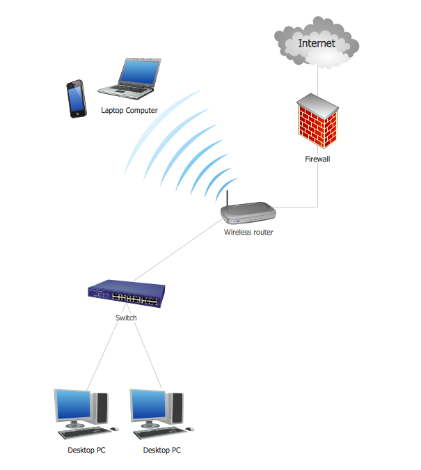
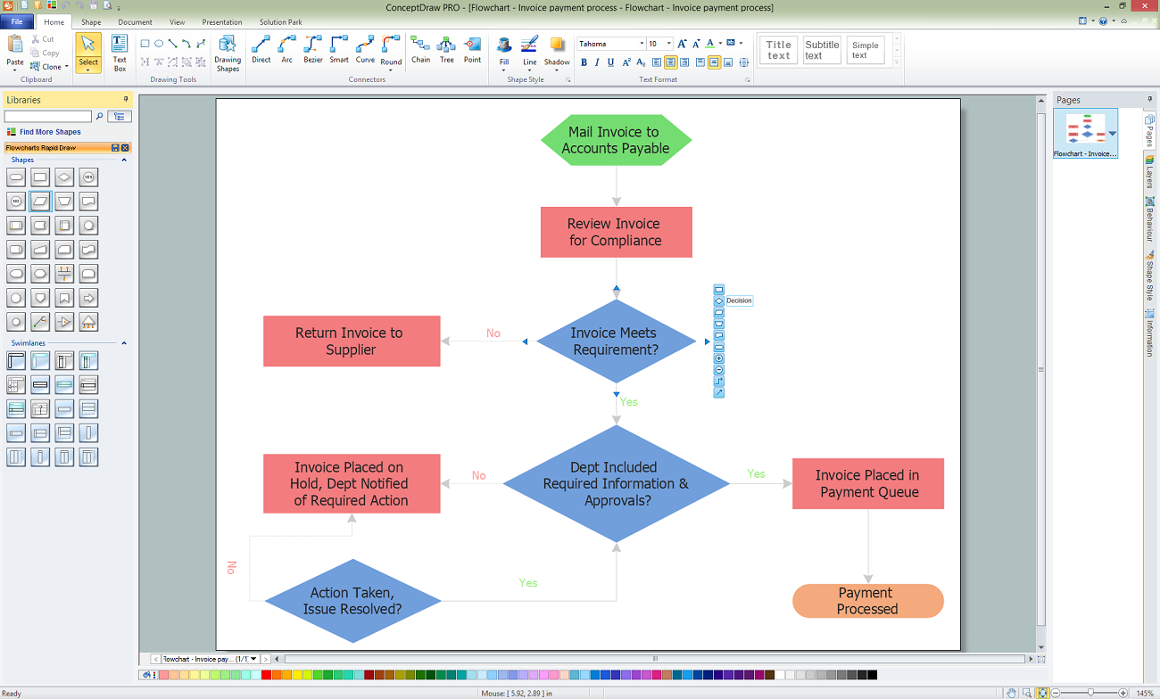
Example 2. Concept Map — Information Systems in the Schools
Simply drag the needed shapes from thelibrary on your map, arrange and connect them. Don't forget to use the colors to make the Concept Map attractive and successful. You can also additionally use the predesigned shapes and clipart from other libraries of ConceptDraw Solution Park.

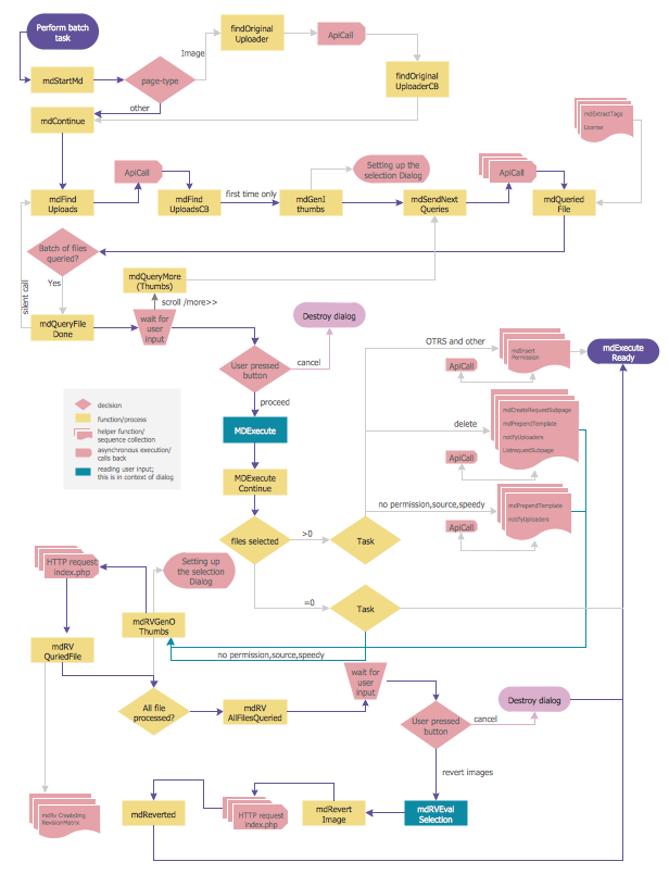
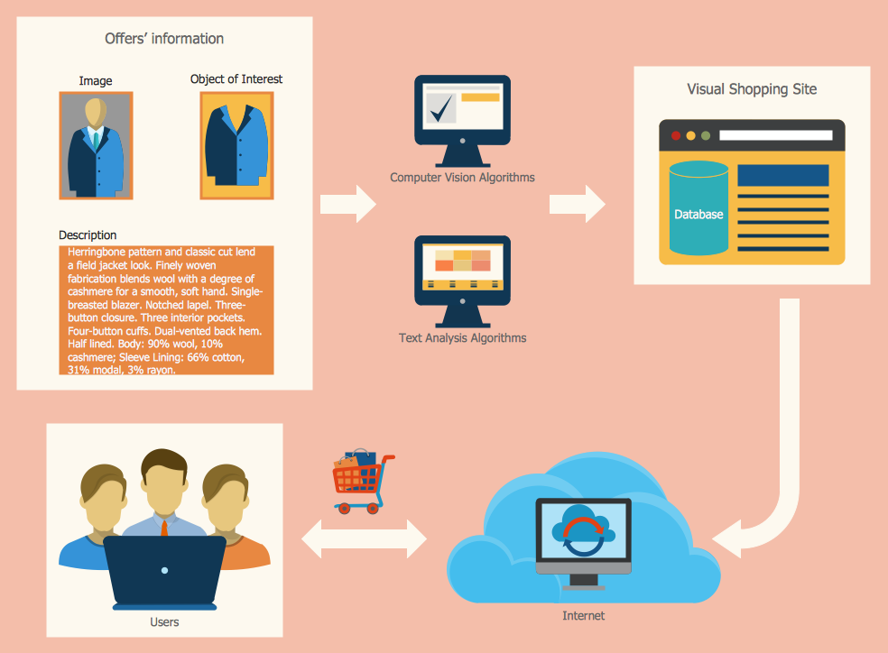
Example 3. Concept Map — Online Shop
If you need to make any concept map, you should be considering using a ConceptDraw DIAGRAM diagramming and drawing software. Having Concept Maps Solution downloaded from a ConceptDraw STORE can be also very beneficial, as the mentioned application is one of the very useful products developed by the team of professions of CS Odessa especially for ConceptDraw DIAGRAM users to offer them to use the pre-made examples of such drawings, as concept maps, as well as the pre-made design elements. Having the mentioned tool means having a lot of templates you can always use to create your own concept maps by editing the existing ones. Such samples as “Concept Map — Online Shop”, “Concept Map — Internet Marketing”, “Concept Map — Team Psychological Characteristics” and “Concept Map — Risk Management” can be always changed the way you want them to be to become the final result as you expect it to be.