Network Printer


The vector stencils library "Network layout floorplan" contain 34 symbol icons for drawing computer network floor plans, communication equipment layouts, and structured cabling diagrams.
"Structured cabling is building or campus telecommunications cabling infrastructure that consists of a number of standardized smaller elements (hence structured) called subsystems. ...
Structured cabling design and installation is governed by a set of standards that specify wiring data centers, offices, and apartment buildings for data or voice communications using various kinds of cable, most commonly category 5e (CAT-5e), category 6 (CAT-6), and fibre optic cabling and modular connectors. These standards define how to lay the cabling in various topologies in order to meet the needs of the customer, typically using a central patch panel (which is normally 19 inch rack-mounted), from where each modular connection can be used as needed. Each outlet is then patched into a network switch (normally also rack-mounted) for network use or into an IP or PBX (private branch exchange) telephone system patch panel." [Structured cabling. Wikipedia]
The design elements example "Network layout floorplan - Vector stencils library" was created using the ConceptDraw PRO diagramming and vector drawing software extended with the Network Layout Floor Plans solution from the Computer and Networks area of ConceptDraw Solution Park.
PC

Scanner

Switch

Router

Modem

Hub

Rack Mount

Printer

Floor Mounted Outlet

Single Outlet

Duplex Outlet

Direct bus cable

Tops or bottoms bus cable

Side to side bus cable

Multi-tree bus cable

Bottom to side bus cable

Sides bus cable

Door

Door, threshold

Door, stop

Door, stop, threshold

Door, frame

Door, frame, threshold

Door, frame, stop

Door, frame, stop, threshold

Window

Window, sill

Window, sash

Window, sash, sill

Window, frame

Window, frame, sill

Window, frame, sash

Window, frame, sash, sill

Cisco Routers. Cisco icons, shapes, stencils and symbols

Any planning begins with an analysis of the business requirements to the final system. Basic network parameters, which should be assessed are the scalability, accessibility, cost, speed and safety.
Speed and cost are often mistaken for the most important parameters, and the rest of the parameters aren't even remembered. This is not entirely correct. Initially, it is necessary to assess the business plans for the future, because sometimes it is more profitable to invest more money in the beginning. If the business is to develop, then, consequently, demands on
The vector stencils library "Computer network" contains 51 symbols of computer network devices and equipment for drawing computer network diagrams.
"Network Mapping Software.
A number of software tools exist to design computer network diagrams / or generate visual maps of networks, servers, storage, services, data centers, and other peripherals. Broadly, there are two types of software tools - those that help create diagrams manually and those that generate them using automated / semi-automated approaches.
Type of Software.
(1) Manual - allows users to design and draw logical and physical topology diagrams by manually placing icons and connections.
(2) Automated - generate topology diagrams / maps by traversing the network and automatically discovering resident devices or by importing network data." [Comparison of network diagram software. Wikipedia]
ConceptDraw PRO is the software for manual design of computer network diagrams. The solutions of the Computer and Networks area in ConceptDraw Solution Park extend ConceptDraw PRO with vector stencils libraries, templates and examples for creating the computer network diagrams.
The symbols example "Computer network - Vector stencils library" was created using the ConceptDraw PRO diagramming and vector drawing software extended with the Computer and Networks solution from the Computer and Networks area of ConceptDraw Solution Park.
www.conceptdraw.com/ solution-park/ computer-and-networks
Laptop

Desktop computer

Firewall

Bus

Ethernet

Star network

FDDI Ring

Token-ring

Comm-link

Modem

Laser printer

Inkjet printer

Image scanner

City

Ethernet hub

Wireless router

Network switch

iPod Classic

iPhone/ iPod Touch

Xserve RAID

XServe

Apple Thunderbolt Display

Data store

Mac Pro

iMac

RAID

Mainframe

Rack-mountable server

Server

PDA

Cloud

Computer monitor

Workstation

Router

IP Phone

Fax

Mobile phone

Smartphone

Compact Disk

Mouse

Apple Wireless Mouse

Computer keyboard

Apple Keyboard

Radio tower

Satellite dish

Satellite

Webcam

AirPort Extreme

Airport Express

MacBook

iPhone 4

This network layout floorplan example was drawn on the base of the picture "Ethernet cable layout" illustrating "UGA Technical Network Liaison Handbook" from the website of the University of Georgia.
[netinfo.uga.edu/ tnlhand/ landiag.gif]
"The Ethernet physical layer is the physical layer component of the Ethernet family of computer network standards.
The Ethernet physical layer evolved over a considerable time span and encompasses quite a few physical media interfaces and several magnitudes of speed. The speed ranges from 1 Mbit/ s to 100 Gbit/ s, while the physical medium can range from bulky coaxial cable to twisted pair and optical fiber. In general, network protocol stack software will work similarly on all physical layers.
10-gigabit Ethernet was already used in both enterprise and carrier networks by 2007, with 40 Gbit/ s and 100 Gbit/ s Ethernet ratified." [Ethernet physical layer. Wikipedia]
The network layout floorplan example "Ethernet cable layout" was created using the ConceptDraw PRO diagramming and vector drawing software extended with the Network Layout Floor Plans solution from the Computer and Networks area of ConceptDraw Solution Park.
Network layout floorplan

EIGRP. Computer and Network Examples
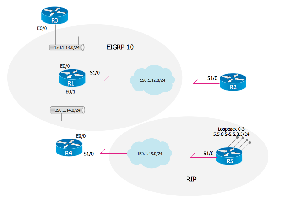
EIGRP is used to help automate routing decisions and configuration of the computer network. It allows the routers of the same logical area automatically share route information.
How To use Switches in Network Diagram

Use ConceptDraw DIAGRAM with Computer & Networks solution for drawing LAN and WAN topology and configuration diagrams, Cisco network diagrams, network wiring schemes and floor plan layouts.
Star Network Topology

Use it to draw the physical and logical network topology diagrams for wired and wireless computer communication networks.

Network Glossary Definition

Easy to draw network topology diagrams, network mapping and Cisco network topology.
The vector stencils library "Cisco LAN" contains 23 symbols of local area network (LAN) devices and equipment for drawing Cisco LAN topology diagrams.
"Network topology describes the layout of interconnections between devices and network segments. At the Data Link Layer and Physical Layer, a wide variety of LAN topologies have been used, including ring, bus, mesh and star, but the most common LAN topology in use today is switched Ethernet. At the higher layers, the Internet Protocol (TCP/ IP) has become the standard, replacing NetBEUI, IPX/ SPX, AppleTalk and others.
Simple LANs generally consist of one or more switches. A switch can be connected to a router, cable modem, or ADSL modem for Internet access. Complex LANs are characterized by their use of redundant links with switches using the spanning tree protocol to prevent loops, their ability to manage differing traffic types via quality of service (QoS), and to segregate traffic with VLANs. A LAN can include a wide variety of network devices such as switches, firewalls, routers, load balancers, and sensors.
LANs can maintain connections with other LANs via leased lines, leased services, or the Internet using virtual private network technologies. Depending on how the connections are established and secured in a LAN, and the distance involved, a LAN may also be classified as a metropolitan area network (MAN) or a wide area network (WAN)." [Local area network. Wikipedia]
The symbols example "Cisco LAN - Vector stencils library" was created using the ConceptDraw PRO diagramming and vector drawing software extended with the Cisco Network Diagrams solution from the Computer and Networks area of ConceptDraw Solution Park.
www.conceptdraw.com/ solution-park/ computer-networks-cisco
Sun workstation

Workstation

PC

Macintosh

Terminal

Mini VAX

Printer

Laptop

File server

Monitor

Web cluster

ATM fast gigabit etherswitch

HP Mini

Supercomputer

LAN2LAN

LAN to LAN

Web server

Web browser

Repeater

PDA

General appliance

PC, blue

Mini VAX, blue

Local area network (LAN). Computer and Network Examples
 diagram")
ConceptDraw - Perfect Network Diagramming Software with examples of LAN Diagrams. ConceptDraw Network Diagram is ideal for network engineers and network designers who need to draw Local Area Network diagrams.
Metropolitan area networks (MAN). Computer and Network Examples
. Computer and Network Examples")
Network Hubs

Mesh Network Topology Diagram

The Mesh Network Topology Diagram examples was created using ConceptDraw DIAGRAM software with Computer and Networks solution.
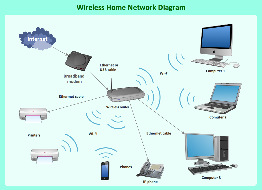
What Is a Wireless Network?
- Network Printer | Network diagrams with ConceptDraw PRO | How to ...
- Network Printer | Physical LAN topology diagram | Using Both Wired ...
- Wireless router network diagram | What Is a Wireless Network ...
- Computer Router Switch Diagram
- How To use Switches in Network Diagram | Star Network Topology ...
- Wireless Network Pc Server Router
- Pc Router Diagram
- Network Layout Floor Plans | Ethernet cable layout | Ethernet local ...
- Network Printer | Wireless access point - Network diagram | Wireless ...
- Star Network Topology | Network Topologies | Fully Connected ...
- How To Set A Lay Out Using Router Server Pc And Switch
- Wireless router network diagram | Cisco Routers. Cisco icons ...
- Network Gateway Router | Network Printer | Network Diagram ...
- Using Both Wired and Wireless Connections | Fully Connected ...
- Network Gateway Router | Computer network - Vector stencils library ...
- Computer network - Vector stencils library | Network Glossary ...
- Network Gateway Router | Hotel Network Topology Diagram | Star ...
- Home area networks (HAN). Computer and Network Examples ...
- Network Printer | Wireless access point - Network diagram | Home ...
- Star Network Topology | Fully Connected Network Topology ...
- ERD | Entity Relationship Diagrams, ERD Software for Mac and Win
- Flowchart | Basic Flowchart Symbols and Meaning
- Flowchart | Flowchart Design - Symbols, Shapes, Stencils and Icons
- Flowchart | Flow Chart Symbols
- Electrical | Electrical Drawing - Wiring and Circuits Schematics
- Flowchart | Common Flowchart Symbols
- Flowchart | Common Flowchart Symbols