Ring Network Topology

Bus Network Topology

Use it to draw the physical and logical network topology diagrams for wired and wireless computer communication networks.
Create your bus network topology diagrams using the ConceptDraw DIAGRAM.
Using Both Wired and Wireless Connections
Network Topology

10Base-T Star Network Topology
Bus Topology Diagram
Common Network Topologies
Fully Connected Network Topologies
Ring Network Topologies
Mesh Network Topologies
With more than 2 000 pre-designed network elements you can design own Network Topology of the simple LAN, WAN, etc.

Personal area (PAN) networks. Computer and Network Examples
 networks")
This example was created in ConceptDraw DIAGRAM using the Computer and Networks Area of ConceptDraw Solution Park and shows the Personal area network.
Network Glossary Definition

Easy to draw network topology diagrams, network mapping and Cisco network topology.
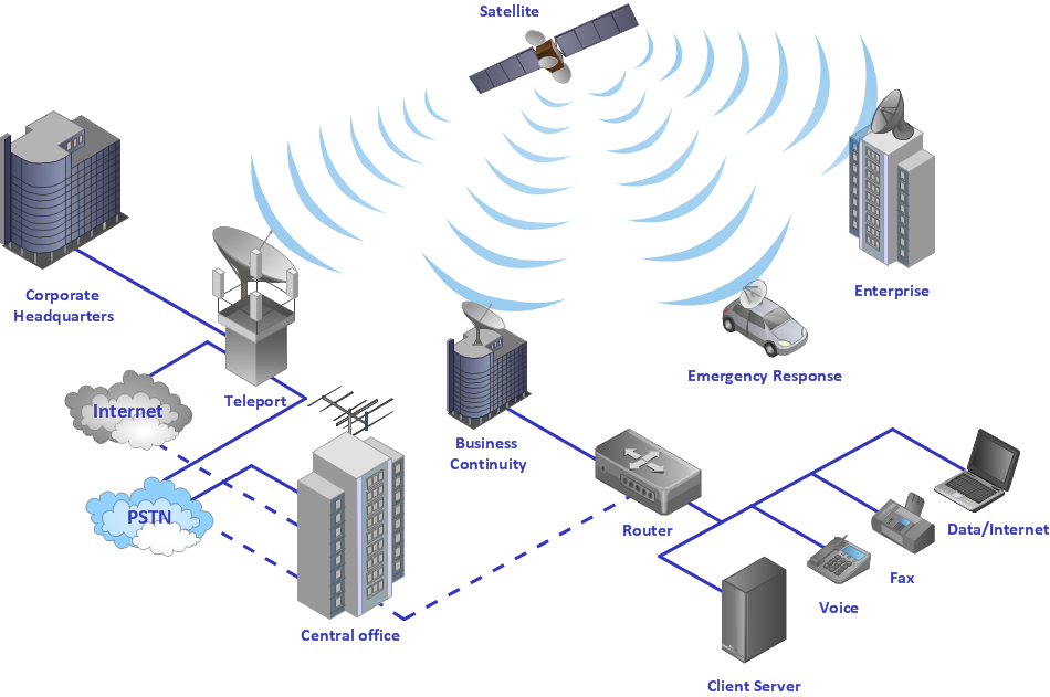
Cable Network. Computer and Network Examples

 Computer Network Diagrams
Computer Network Diagrams solution extends ConceptDraw DIAGRAM software with samples, templates and libraries of vector icons and objects of computer network devices and network components to help you create professional-looking Computer Network Diagrams, to plan simple home networks and complex computer network configurations for large buildings, to represent their schemes in a comprehensible graphical view, to document computer networks configurations, to depict the interactions between network's components, the used protocols and topologies, to represent physical and logical network structures, to compare visually different topologies and to depict their combinations, to represent in details the network structure with help of schemes, to study and analyze the network configurations, to communicate effectively to engineers, stakeholders and end-users, to track network working and troubleshoot, if necessary.
Electrical Symbols — Transmission Paths
26 libraries of the Electrical Engineering Solution of ConceptDraw DIAGRAM make your electrical diagramming simple, efficient, and effective. You can simply and quickly drop the ready-to-use objects from libraries into your document to create the electrical diagram.
Physical network. Computer and Network Examples
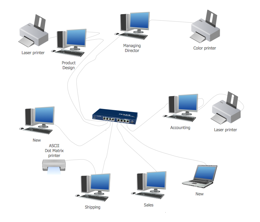
This example was created in ConceptDraw DIAGRAM using the Computer and Networks Area of ConceptDraw Solution Park and shows the Physical star network.
- Fully Connected Topology Advantages And Disadvantages
- Daisy Chain Topology Advantages And Disadvantages
- Daisy Chaining Advantage And Disadvantage
- Daisy Chain Topology Advantage And Disadvantage
- Point to Point Network Topology | Fully Connected Network ...
- Logical Topology Advantages And Disadvantages Of Logical
- Fully Connected Network Topology Diagram | Ring Network ...
- Advantages And Disadvantages Of Personal Area Network Article
- Extended Star Topology Advantages And Disadvantages
- Daisy Chain Network Advantage And Disadvantage
- ERD | Entity Relationship Diagrams, ERD Software for Mac and Win
- Flowchart | Basic Flowchart Symbols and Meaning
- Flowchart | Flowchart Design - Symbols, Shapes, Stencils and Icons
- Flowchart | Flow Chart Symbols
- Electrical | Electrical Drawing - Wiring and Circuits Schematics
- Flowchart | Common Flowchart Symbols
- Flowchart | Common Flowchart Symbols