Electrical Symbols — Qualifying
There are several national and international standards for graphical symbols in circuit diagrams, in particular:
- IEC 60617 (also known as British Standard BS 3939)
- IEEE Std 91/91a
- ANSI standard Y32 (also known as IEEE Std 315)
- Australian Standard AS 1102
IEC-60617 Symbols
- Qualifying Symbols
- Operating Devices
- Linear Direction of Force or Motion
- Rotative Direction of Force or Motion
- Propagation Flow or Signal
- Energy Flow
- Effect
- Radiation
- Fault
- Winding
- Mechanical Controls
- Mechanical Controls, Latching Device
- Mechanical Controls, Coupling

Pic. 1. Qualifying Library
ConceptDraw DIAGRAM is a powerful software for creating professional looking electrical diagram quick and easy. For this purpose you can use the Electrical Engineering solution from the "Engineering" area of ConceptDraw Solution Park.
Electrical Engineering Solution for ConceptDraw DIAGRAM provides the stencils libraries of ready-to-use predesigned 926 vector symbols, templates and samples that make your electrical drawing quick, easy and effective.
26 libraries of the Electrical Engineering Solution of ConceptDraw DIAGRAM make your electrical diagramming simple, efficient, and effective. You can simply and quickly drop the ready-to-use objects from libraries into your document to create the electrical diagram.

Pic. 2. Electrical Engineering symbols
Electrical diagram software will assist you in drawing your electrical diagrams with minimal effort and makes it very easy for beginners.
Electrical symbols and smart connectors help present your electrical drawings, electrical schematic, wiring diagrams and blue prints.

Pic. 3. Electrical Symbols — Qualifying
Most of the electrical symbols can be changed in their appearance, styles and colors according to users' requirements. Electrical symbols are used to represent various electrical and electronic devices in a schematic diagram of an electrical or electronic circuit.
The following table lists some qualifying electrical symbols in our electrical diagram software.
| Symbol |
Meaning |
| Electrical Symbols — Qualifying |
 | Radiation, non-ion. |
 | Radiation, ion. |
 | Radiation, non-ion., coherent |
 | Radiation, ion., coherent |
 | Radiation, non-ion. 2 |
 | Radiation, ion. 2 |
 | Radiation, non-ion., coherent 2 |
 | Radiation, ion., coherent 2 |
 | Positive polarity |
 | Negative polarity |
 | Neutral symbol |
 | Multiple-phase |
 | Multiple-phase 2 |
 | Multiple-phase, interconnect. |
 | Multiple-phase, interconnect. 2 |
 | 3 separate windings |
 | 3 separate windings, interconnect. |
 | 3 separate windings, interconnect. 2 |
 | 2-phase 3-wire |
 | 2-phase 3-wire, separated |
 | 2-phase 3-wire, grounded |
 | 2-phase 3-wire, separat., ground. |
 | 2-phase 4-wire |
 | 2-phase 4-wire, grounded |
") | 3-phase (V) |
") | 3-Phase (T) |
 | 3-phase delta 1 |
 | 3-phase delta 1, grounded |
 | 3-phase delta 2 |
 | 3-phase delta 2, grounded |
 | 3-phase delta 2, grounded 2 |
 | 3-phase delta 3 |
 | 3-phase delta 4 |
 | 3-phase delta 4, grounded |
 | 3-phase star, general |
 | 3-phase star, grounded |
 | 3-phase star, neutral brought out |
 | 3-phase zigzag |
 | 3-phase zigzag, grounded |
 | 3-phase 4-wire, general |
 | 3-phase 4-wire, grounded |
 | 3-phase 4-wire, neutral brought out |
 | 4-phase, general |
 | 4-phase, grounded |
 | 4-phase, neutral brought out |
 | 6-phase double star |
 | 6-phase double star, grounded |
 | 6-phase double star 2 |
 | 6-phase double star, grounded 2 |
 | 6-phase double delta |
 | 6-phase polygon |
 | 6-phase fork |
 | 6-phase fork, neutral |
 | Special connector |
 | Coaxial symbol |
 | Electret |
A qualifying symbol is graphics or text added to the basic outline of a device’s logic symbol to describe the physical or logical characteristics of the device.
How to Create an Electrical Diagram Using Qualifying Library
TEN RELATED HOW TO's:
The most easier way of creating the visually engaging and informative Sales Process Flowchart is to create the new ConceptDraw document and to use the predesigned vector symbols offered in 6 libraries of the Sales Flowchart Solution. There are more than six types of sales process flow diagrams, ConceptDraw DIAGRAM software is flowchart maker which include six collections of extended flowchart symbols for effective diagramming. There are main collections of color coded flowchart symbols: Sales Department, Sales Steps, Sales Workflow, Sales Symbols and special set of Sales Arrows and Sales Flowchart.
Picture: Sales Process Flowchart Symbols
Related Solution:
The Line Graphs solution from Graphs and Charts area of ConceptDraw Solution Park contains a set of examples, templates and design elements library of scatter charts.
Use it to draw scatter graphs using ConceptDraw DIAGRAM diagramming and vector drawing software for illustrating your documents, presentations and websites.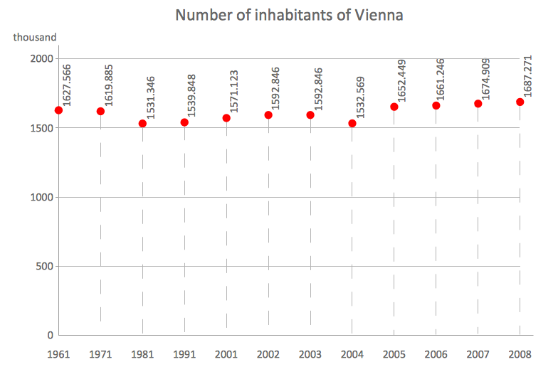
Picture: Scatter Chart Examples
Related Solution:
Beginning from the 19th century, people tried to tame electricity. Nowadays, electrical engineering covers a wide range of applications starting from providing illumination in our homes to developing space technologies. Considering the fact that every project needs documentation, engineers use electrical diagram software to develop these projects. Standard electrical symbols of electrical components are recognizable all around the world.
This illustration represents the 26 libraries that are supplied by the ConceptDraw Electrical Engineering solution. The Electric Engineering libraries contains about a thousand objects enabling you to draw various charts depicting electrical connections and circuits, along with schemes of different equipment and devices. The electric engineering libraries delivered with ConceptDraw solution meet the standards adopted in the image to electrical circuits. So they can be used by professionals along with amateurs in electrical engineering.
Picture: Electrical Diagram Software
Related Solution:
A flowchart is a powerful tool for examining processes. It helps improving processes a lot, as it becomes much easier to communicate between involved people, to identify potential problems and to optimize workflow. There are flowcharts of different shapes, sizes and types of flowchart vary from quite basic process flowcharts to complex program flowcharts. Nevertheless, all these diagrams use the same set of special symbols like arrows to connect blocks, parallelogram to show data receiving or rectangles for showing process steps.
Basic flowcharts are used to represent a simple process algorithm. A basic flowchart notation consists of rectangles (business processes), arrows (the flow of information, documents, etc.). The same notation is used in items such as the "decision", which allow you to do the branching. To indicate the start of the entire business process and its termination can be used the "Terminator" element. The advantages of Basic Flowchart are simplicity and clarity. With it you can quickly describe the business process steps. Creating of Basic Flowchart does not require any special knowledge, as easily understand by employees with different levels of education and IQ.
Picture: Types of Flowchart - Overview
Related Solution:
Mechanical design is a labour-intensive process. To facilitate the task of Mechanical Engineering Diagrams creating, ConceptDraw DIAGRAM diagramming and vector drawing software was extended with Mechanical Engineering solution from the Engineering area. Now, ConceptDraw DIAGRAM is a powerful Mechanical Design Software.
Picture: Mechanical Design Software
Related Solution:
It’s very simple, convenient and quick to design professional looking Flowcharts of any complexity using the ConceptDraw DIAGRAM diagramming and vector drawing software extended with Flowcharts Solution from the "Diagrams" Area of ConceptDraw Solution Park which provides a wide set of predesigned objects, templates, samples and Flowchart examples.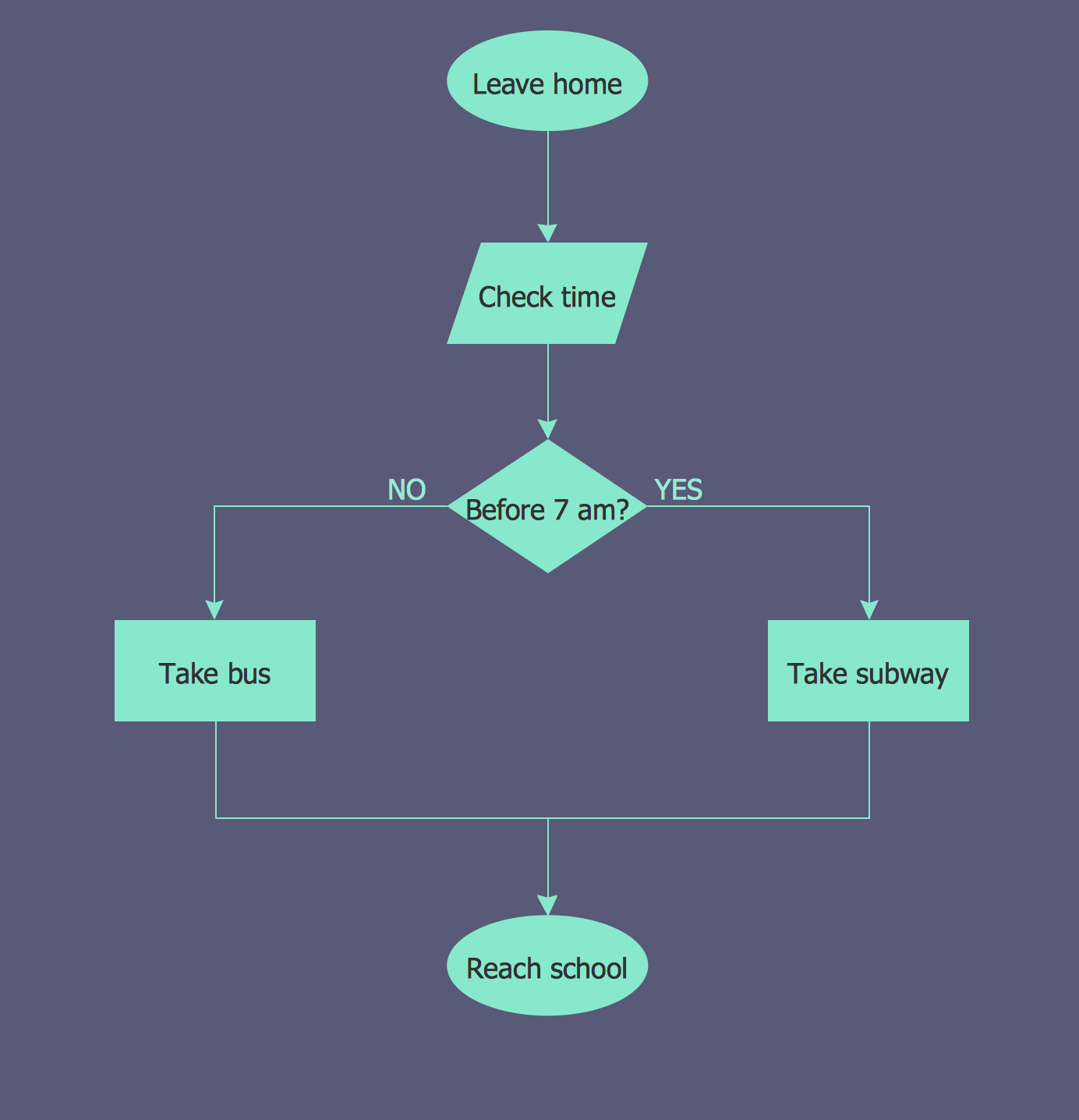
Picture: Flowchart Examples
Related Solution:
Electrical engineering is a field of engineering that generally deals with the study and application of electricity, electronics, and electromagnetism. ConceptDraw DIAGRAM extended with Electrical Engineering Solution from the Industrial Engineering Area of ConceptDraw Solution Park is the best Electrical Engineering software. You have an excellent possibility to make sure this right now.
Picture: Electrical Engineering
Related Solution:
The digital communication is a physical transfer of the data over a point-to-point or point-to-multipoint communication channel. Channels can be copper wires, optical fibres, wireless communication channels, etc. The data are realized as electromagnetic signals (radiowave, microwave, electrical voltage, etc.).
This example was created in ConceptDraw DIAGRAM using the Computer and Networks Area of ConceptDraw Solution Park and shows the Digital Communication Network diagram.
Picture: Digital Communications Network. Computer and Network Examples
Related Solution:
The excellent possibility to create attractive Cross Functional Flowcharts for step-by-step visualization the operations of a business process flow of any degree of detailing is offered by ConceptDraw’s Cross-Functional Flowcharts solution. The extensive selection of commonly used vector cross functional flowchart symbols allow you to demonstrate the document flow in organization, to represent each team member’s responsibilities and how processes get shared or transferred between different teams and departments.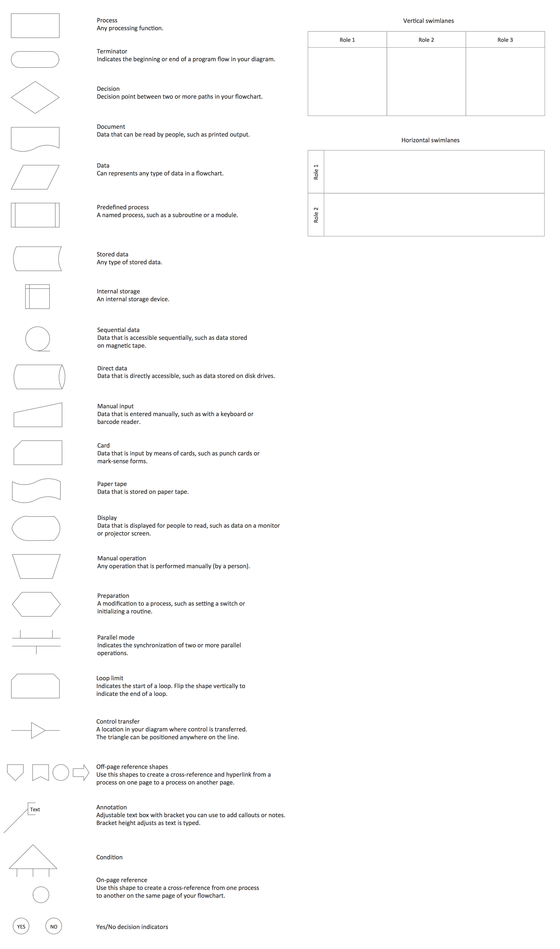
Picture: Cross Functional Flowchart Symbols
Related Solution:


 . To connect elements using this tool, drag the connector from one connect dot to another.You can use Layers to place connections on different layers.

