Flowchart Examples
Flowchart examples help explain how processes actually work. By looking at real diagrams, it becomes easier to understand how steps connect, where decisions occur, and how work moves from one stage to the next, including cross-functional workflows such as swimlane diagrams.
Quick flowchart examples: simple flowchart example, swimlane flowchart example.
This page collects practical flowchart examples, common diagram patterns, and typical industry workflows. You can explore diagrams by type, review reusable process patterns, or see how different industries structure their workflows.
If you are new to the topic, start with our complete flowchart guide. For symbol definitions, see the flowchart symbols reference; for layout guidance, review flowchart design best practices; and for building your own diagrams, explore flowchart software.
Quick answer: A flowchart example shows how a process moves from start to finish using standardized symbols, decision points, and directional flow. Common examples include simple process diagrams, business workflows, cross-functional swimlane diagrams, and technical troubleshooting flows.
Common flowchart examples include:
- Simple process flowchart
- Business process flowchart
- Workflow diagram
- IT troubleshooting flowchart
- Swimlane flowchart
Each example highlights a different way processes can be structured, helping you recognize common workflow patterns and apply standard flowchart symbols correctly when creating your own diagrams.
Flowchart Examples by Use Case
Use this table to quickly choose a flowchart example based on what you need to document.
| Example Type | Description | Typical Use |
|---|---|---|
| Basic Flowchart | Shows a simple step-by-step sequence with minimal branching. | Simple procedures, onboarding, routine tasks |
| Business Process Flowchart | Visualizes operational procedures and approval paths. | SOP documentation, operations management |
| Workflow Diagram | Shows how tasks move between roles or departments. | Team coordination and task management |
| IT Troubleshooting Flowchart | Represents diagnostic logic and decision-based support paths. | Technical support, system checks, problem solving |
| Cross-Functional Flowchart | Displays responsibilities across departments using swimlanes. | Organizational process documentation |
Once you know which type of process you want to document, it helps to review a few visual examples before moving into more detailed explanations.
In short: use a basic flowchart for simple procedures, a business process flowchart for structured operations, a workflow diagram for task movement, a troubleshooting flowchart for diagnostics, and a swimlane flowchart for cross-functional responsibilities.
Common flowchart example types include simple process diagrams, business process workflows, approval workflows, troubleshooting flowcharts, and cross-functional swimlane diagrams.
Example Gallery
The gallery below works as a quick visual index of common diagram formats. Use it to compare example types before reviewing the detailed explanations further down the page.

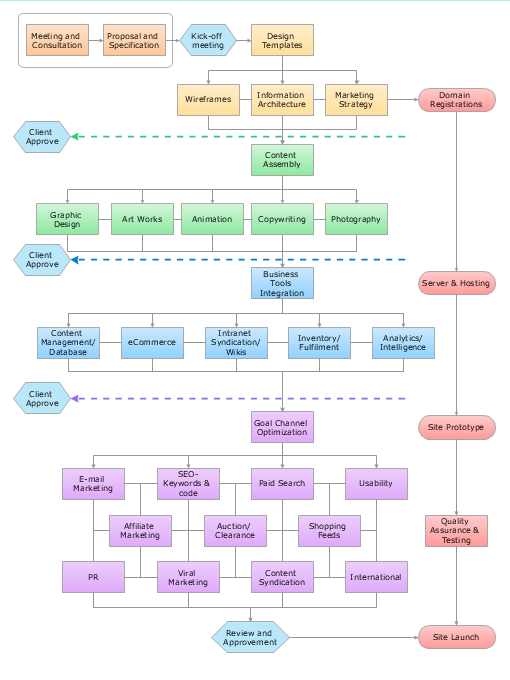
This business process flowchart shows how an operational workflow moves through structured steps, checks, and approvals.

This workflow diagram example shows how a task moves through review, approval, revision, and completion steps.

This IT troubleshooting flowchart shows a structured approach to diagnosing technical problems step by step.

This swimlane flowchart shows how responsibilities move across departments in a cross-functional process.
The gallery above provides a quick comparison of common formats. The table below offers direct access to each example type before the detailed explanations begin.
Example Types
The table below provides quick access to the main examples covered on this page.
| Flowchart Type | What It Shows | Jump to Example |
|---|---|---|
| Basic Flowchart | Simple sequence of process steps | View example |
| Business Process Flowchart | Operational workflow with approvals | View example |
| Workflow Diagram | Task movement between roles or teams | View example |
| IT Troubleshooting Flowchart | Diagnostic logic and technical decision paths | View example |
| Swimlane Flowchart | Responsibilities across departments | View example |
Examples by Type
Different types of flowcharts are used depending on the complexity of a process and the level of detail required. Some diagrams focus on simple step-by-step logic, while others show role responsibilities, approvals, or technical diagnostic paths.
Before building complex diagrams, it is helpful to review the flowchart symbols reference.
The sections below explain the main flowchart formats in more detail, including what each type shows, when to use it, and which symbols typically appear in the diagram.
Basic Flowchart Example
A basic flowchart represents the simplest form of process visualization. It shows a sequence of actions arranged in a clear, linear structure with a defined starting point and a final outcome.
What this example shows: A simple start-to-finish process with minimal branching.
When to use:
- Documenting a straightforward procedure
- Explaining a process to new team members
- Creating a quick visual checklist of steps
Key symbols used: Terminator, Process, Arrow, and optional Decision.
Typical use cases: onboarding steps, simple SOPs, recurring routines.

View full-size flowchart example
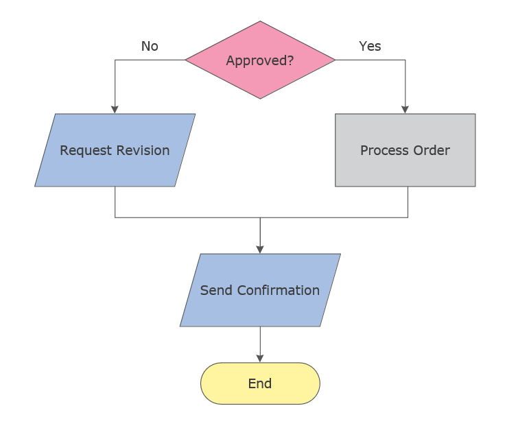
This simple flowchart example shows how a decision point splits a process into two clear paths before completion.
Learn more about basic process structure in our flowchart guide.
Business Process Flowchart
A business process flowchart illustrates how work moves through a structured operational procedure. These diagrams often include validation steps, approval points, and handoffs between departments.
What this example shows: An operational procedure with multiple steps, checks, and possible approvals.
When to use:
- Standardizing operational processes
- Clarifying approvals, validations, and handoffs
- Identifying bottlenecks in a procedure
Key symbols used: Process, Decision, Document, and Connector.
Typical use cases: invoice approval, procurement, order processing, service delivery.
View full-size flowchart example
This business process flowchart shows how an operational workflow moves through structured steps, checks, and approvals.
Learn more about the standard shapes used in this diagram in our process flowchart symbols guide.
Workflow Diagram Example
A workflow diagram focuses on the movement of tasks between roles, teams, or systems. Unlike a simple linear diagram, workflow diagrams emphasize responsibility and handoffs.
What this example shows: How tasks move between roles or teams across a repeatable workflow.
When to use:
- Clarifying role handoffs and ownership
- Mapping repeatable team routines
- Reducing ambiguity in who does what next
Key symbols used: Process, Decision, Connectors, and optional Swimlanes.
Typical use cases: content review, request handling, bug triage, approval workflows.
View full-size flowchart example
This workflow diagram example shows how a task moves through review, approval, revision, and completion steps.
See how similar process diagrams are structured in our flowchart guide.
IT Troubleshooting Flowchart Example
An IT troubleshooting flowchart represents diagnostic logic, support paths, and conditional checks used to identify and resolve technical problems.
What this example shows: Conditional logic that branches based on technical checks and outcomes.
When to use:
- Troubleshooting and diagnostics
- Technical support documentation
- Problem-solving routines with yes/no decisions
Key symbols used: Decision, Process, Connector, and optional Off-page Connector.
Typical use cases: IT support guides, network checks, software issues, technical escalation paths.
View full-size flowchart example
This IT troubleshooting flowchart shows a structured approach to diagnosing technical problems step by step.
Learn how decision shapes and connectors work in our flowchart symbols reference.
Swimlane Flowchart Example
A swimlane flowchart organizes a process into horizontal or vertical lanes representing roles, departments, or systems. Each lane shows who is responsible for a particular step.
What this example shows: A process split into lanes to show responsibilities across roles or departments.
When to use:
- Documenting cross-functional processes
- Showing handoffs between teams
- Reducing confusion in multi-owner workflows
Key symbols used: Swimlane containers, Process, Decision, and Connector.
Typical use cases: order fulfillment, support escalation, HR approvals, cross-team delivery.
View full-size flowchart example
This swimlane flowchart example shows how responsibilities move across departments in a cross-functional process.
Learn how to organize cross-functional layouts in our flowchart design guide.
Although these examples differ by purpose and structure, many of them rely on the same recurring logic. The next section summarizes the most common flowchart patterns used across business and technical diagrams.
Flowchart Patterns
Many process diagrams follow recurring structural patterns. These patterns represent common ways processes are organized, such as approval loops, conditional decisions, parallel task execution, and exception handling.
Recognizing patterns helps teams design diagrams faster and stay consistent across documentation. For layout and readability guidance, see flowchart design best practices.
Flowchart Pattern Table
| Pattern | What it’s for | Common symbols | Typical Use |
|---|---|---|---|
| Linear Steps | Single-path procedures with a clear sequence | Start/End, Process, Arrow | Checklists, simple SOPs |
| Decision Branch | Conditional routing based on a rule | Decision, Process, Connector | Validation, eligibility checks |
| Approval Loop | Review until approved | Decision, Process, Loop Arrow | Finance, legal, publishing |
| Exception Path | Alternative steps on error or special case | Decision, Connector, Process | Support, operations handling |
| Parallel Tasks | Workstreams that proceed at the same time | Split paths, Connectors | Project delivery, coordination |
| Role Handoff | Transitions between people or teams | Swimlanes, Process, Connector | Cross-functional operations |
| Rework Loop | Fix and resubmit until criteria are met | Decision, Process, Loop Arrow | QA, approvals, revisions |
| Escalation Path | Routing to higher support or authority | Decision, Connector, Sub-process | Incidents, support workflows |
In practice, most business and technical diagrams combine several of these patterns rather than relying on only one structure.
These same patterns appear in different industries, where they are adapted to specific operational needs, compliance requirements, and role structures.
Industry Flowchart Examples
Different industries use flowcharts to document structured workflows, approval paths, handoffs, and recurring operational routines. The examples below show how similar diagram logic is applied in different professional contexts.
HR Flowchart Examples
HR teams use flowcharts to standardize people-related workflows and reduce ambiguity in approval-based processes.
- Hiring pipeline
- Employee onboarding
- Leave request approval

View full-size flowchart example
This payroll workflow diagram shows how HR and payroll steps can be documented across multiple roles.
Build similar workflow diagrams using flowchart software.
IT Flowchart Examples
IT workflows often rely on conditional logic, escalation paths, and repeatable support routines.
- Bug triage workflow
- Incident response
- Release workflow
Logistics Flowchart Examples
Logistics diagrams help visualize movement, handoffs, and operational checkpoints across fulfillment processes.
- Order fulfillment
- Returns handling
- Inventory restock
Healthcare Flowchart Examples
Healthcare flowcharts are useful for documenting structured procedures, patient movement, and compliance-sensitive workflows.
- Patient intake
- Lab test workflow
- Discharge process
Once you identify the example structure that best matches your workflow, the fastest next step is to start from a template and adapt it to your process.
Common Flowchart Template Types
Common flowchart template types provide structured starting points for documenting processes. Instead of building a diagram from scratch, each template category offers a ready layout with standard symbols and common process steps.
These reusable starting points are especially useful for recurring workflows where the structure remains similar but the details change.
Common Flowchart Template Types
- Basic process template
- Business workflow template
- Decision tree template
- Cross-functional (swimlane) template
- System process template
Most teams start with a template and then customize steps, conditions, and responsibilities based on their workflow.
To work with editable templates and full symbol libraries, specialized diagram tools provide built-in symbol libraries, layout controls, and reusable process templates.
Flowchart Templates
Templates provide a ready-to-use structure that can be quickly adapted to your process. They include consistent spacing, standard symbols, and common layouts that help diagrams stay readable.
If you want to build and customize these examples, explore professional flowchart software with templates and symbol libraries.
- Business process template
- Decision tree template
- Cross-functional workflow template
- System process template
Looking for more ready-made diagram layouts? Browse additional process and workflow templates in the Flowcharts Solution.

|

|

|
Browse the complete Flowcharts Solution for libraries, templates, and example diagrams, or create and customize your own diagrams with ConceptDraw DIAGRAM.
Build any example above using ready templates and standard symbol libraries.
If you prefer a lightweight starting point, you can also download a simple PDF template below or review the FAQ for quick guidance on choosing the right flowchart format.
Need a Flowchart Template?
Download a ready-to-use flowchart template (PDF) and adapt it to your workflow.
Before you choose a template or start building your own diagram, the answers below may help you select the most suitable flowchart format for your task.
Flowchart Examples FAQ
What is the most common type of flowchart?
The most common type is the basic process flowchart, which shows a simple step-by-step sequence from start to finish.
When should I use a swimlane flowchart?
Use a swimlane flowchart when a process involves multiple roles, departments, or teams and responsibility needs to be clearly shown.
What is the difference between a workflow diagram and a business process flowchart?
A workflow diagram emphasizes how tasks move between roles, while a business process flowchart focuses more on structured operational steps, approvals, and controls.
What is an IT troubleshooting flowchart used for?
An IT troubleshooting flowchart is used to represent conditional diagnostic logic, such as yes/no branches, problem checks, corrective actions, and escalation paths.
Which diagram type is best for business operations?
In most cases, a business process flowchart is the best choice for business operations because it clearly shows steps, approvals, and handoffs inside a structured workflow.
Can I start from a flowchart template?
Yes. Templates help you start faster by providing a ready structure, standard symbols, and a readable layout that can be adapted to your process.
Do I need standard symbols for all flowchart examples?
Using standard symbols is strongly recommended because it makes diagrams easier to read, share, and maintain across teams. Standard shapes also improve consistency between examples and final working diagrams.
What do flowchart templates include?
Flowchart templates typically include a predefined layout, standard shapes, and a basic process structure that can be customized for a specific workflow.
Create Your Own Flowchart
All flowchart examples on this page can be recreated using standard symbols, templates, and diagram libraries.
Create and customize your own diagrams using ConceptDraw DIAGRAM.
No subscription required. Runs locally on Mac and Windows.
Related resources: Flowchart guide · Flowchart symbols · Flowchart design · Flowchart software