Electrical Symbols — Transformers and Windings

The vector stencils library "Transformers and windings" contains 29 element symbols of transformers, windings, couplers, metering devices, transductors, magnetic cores, chokes, and a variometer.
Use it to design the electromechanical device schematics and electronic circuit diagrams.
"A transformer is an electrical device that transfers energy between two circuits through electromagnetic induction. Transformers may be used in step-up or step-down voltage conversion, which 'transforms' an AC voltage from one voltage level on the input of the device to another level at the output terminals. This special function of transformers can provide control of specified requirements of current level as an alternating current source, or it may be used for impedance matching between mismatched electrical circuits to effect maximum power transfer between the circuits.
A transformer most commonly consists of two windings of wire that are wound around a common core to induce tight electromagnetic coupling between the windings. The core material is often a laminated iron core. The coil that receives the electrical input energy is referred to as the primary winding, while the output coil is called the secondary winding.
An alternating electric current flowing through the primary winding (coil) of a transformer generates an electromagnetic field in its surroundings and a varying magnetic flux in the core of the transformer. By electromagnetic induction this magnetic flux generates a varying electromotive force in the secondary winding, resulting in a voltage across the output terminals. If a load impedance is connected across the secondary winding, a current flows through the secondary winding drawing power from the primary winding and its power source." [Transformer. Wikipedia]
"An electromagnetic coil (or simply a "coil") is formed when a conductor is wound around a core or form to create an inductor or electromagnet. When electricity is passed through a coil, it generates a magnetic field. One loop of wire is usually referred to as a turn or a winding, and a coil consists of one or more turns. For use in an electronic circuit, electrical connection terminals called taps are often connected to a coil. Coils are often coated with varnish or wrapped with insulating tape to provide additional insulation and secure them in place. A completed coil assembly with one or more set of coils and taps is often called the windings.
Windings are used in transformers, electric motors, inductors, solenoids, loudspeakers, and many other applications." [Electromagnetic coil. Wikipedia]
The shapes example "Design elements - Transformers and windings" was drawn using the ConceptDraw PRO diagramming and vector drawing software extended with the Electrical Engineering solution from the Engineering area of ConceptDraw Solution Park.
Transformer and winding symbols

Sales Process Flowchart Symbols

Cisco Switches and Hubs. Cisco icons, shapes, stencils and symbols
")
Electrical Symbols — Inductors

Cisco Routers. Cisco icons, shapes, stencils and symbols
 Router subdued Router-with-silicon-switch Wavelength-router NetFlow-router uBR910 Broadband-router Gigabit-switch-ATM-tag-router ATM-tag-switch-router Edge-label-switch-router Edge-label-switch-router-with-NetFlow Cisco-7505 Cisco-7507 Cisco-7500-ARS-(7513) Voice-enabled-router TDM-router IP-telephony-router IAD-router Content-service-router Cisco-storage-router Router-with-firewall Wireless-router ASR-1000-series ATM-3800 AXP Cable-modem Ground-terminal. Network equipment refers to hardware devices designed for local area networks, both wired and wireless. Active network equipment is powered from the electricity supply, portable battery, the computer via USB-port and other sources, also it can be used for amplification, conversion and processing of the network signal.")
How To use Appliances Symbols for Building Plan


Value Stream Mapping Symbols

Cisco Telepresence. Cisco icons, shapes, stencils and symbols
")
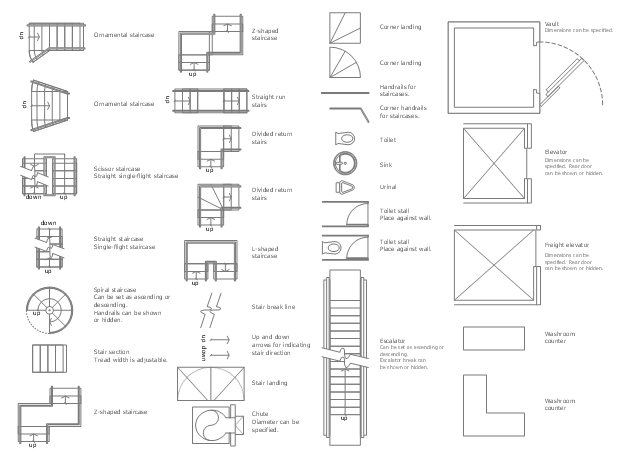
The design elements library Building core contains 80 symbols of stairs, elevators, escalators, restroom fixtures, and a safe.
Use the shapes library Building core to draw the structural diagrams, bathroom layouts, building automation, architectural drawings, and riser diagrams, as well as space plans, store and shopping mall plans, and facility planning, plant layouts using the ConceptDraw PRO diagramming and vector drawing software.
"In architecture and building engineering, a floor plan otherwise known as a Scottish plan is a drawing to scale, showing a view from above, of the relationships between rooms, spaces and other physical features at one level of a structure.
The term may be used in general to describe any drawing showing the physical layout of objects.
A floor plan could show:
Interior walls and hallways;
Restrooms;
Windows and doors;
Appliances such as stoves, refrigerators, water heater etc.;
Interior features such as fireplaces, saunas and whirlpools;
The use of all rooms shall be indicated." [Floor plan. Wikipedia]
The vector stencils library Building core is provided by the Floor Plans solution from the Building Plans area of ConceptDraw Solution Park.
How To use House Electrical Plan Software


Cisco Optical. Cisco icons, shapes, stencils and symbols
")
BPMN 2.0

Cisco Security. Cisco icons, shapes, stencils and symbols
")
Cisco Network Topology. Cisco icons, shapes, stencils and symbols
")
- Circuit Symbol For Laminated Core Inductor
- Design elements - Building core | Architectural Symbols For ...
- Core Network Symbol
- Design elements - Building core | Symbols For Toilet Urinal Etc On A ...
- Magnetic Core Symbol
- Electrical Symbols , Electrical Diagram Symbols | Design elements ...
- Electrical Symbols , Electrical Diagram Symbols | Electrical Symbols ...
- Symbol Of Transformer Magnetic Core
- Design elements - Appliances | Design elements - Building core ...
- Design elements - Building core | Symbols Of Urinal On A Floor Plan
- ERD Symbols and Meanings | Design elements - Transformers and ...
- Toilet Symbol For Technical Drawing
- Electrical Symbols , Electrical Diagram Symbols | Transformers and ...
- Electrical Symbols — Transformers and Windings | Transformers ...
- Cisco Network Topology. Cisco icons, shapes, stencils and symbols ...
- Electrical Symbols — Transformers and Windings | Transformers ...
- Electrical Symbols — Power Sources | Electrical Symbols — Thermo ...
- Electrical Symbols — Rotating Equipment | Design elements ...
- Architectural Symbols For Doors And Windows
- Electrical Symbols , Electrical Diagram Symbols | Electrical Drawing ...