Diagramming Software for Design UML Package Diagrams


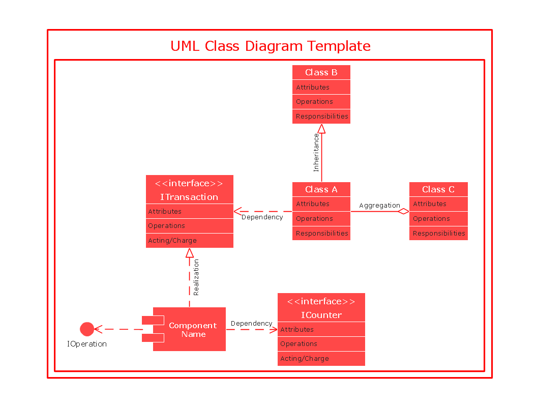
UML Class Diagrams. Diagramming Software for Design UML Diagrams

Diagramming Software for Design UML Collaboration Diagrams

UML Deployment Diagram. Diagramming Software for Design UML Diagrams

UML Component Diagram

UML Notation

Diagramming Software for Design UML Object Diagrams

Diagramming Software for Design UML Activity Diagrams

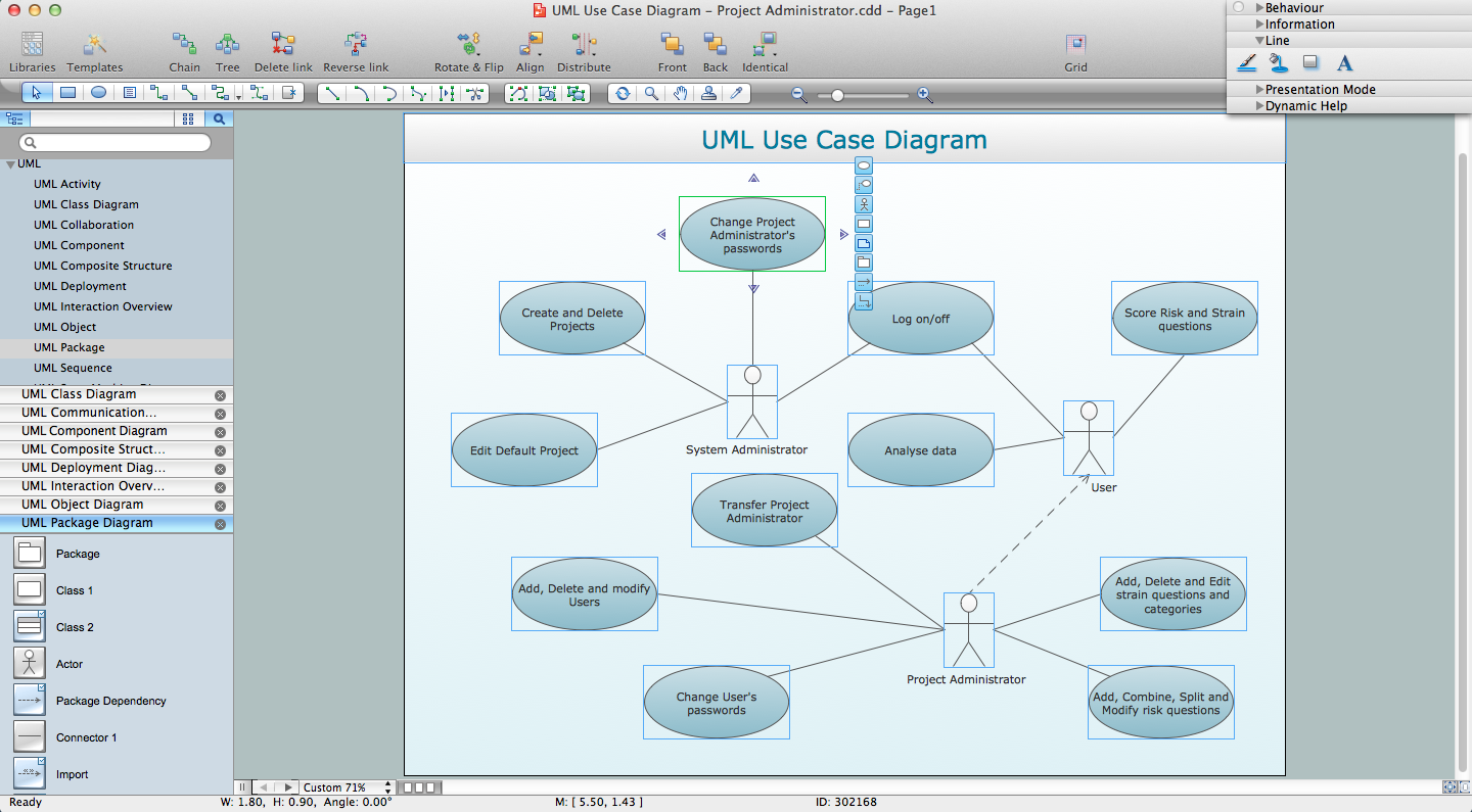
UML Use Case Diagrams

UML Deployment Diagram
UML Class Diagram Notation

UML Class Diagram
Diagramming Software for designing UML Sequence Diagrams

Diagramming Software for Design UML Component Diagrams

UML Diagramming Software

Diagramming Software for Design UML Interaction Overview Diagrams

Diagramming Software for Design UML Use Case Diagrams

 Entity-Relationship Diagram (ERD)
Entity-Relationship Diagram (ERD) solution extends ConceptDraw DIAGRAM software with templates, samples and libraries of vector stencils from drawing the ER-diagrams by Chen's and crow’s foot notations.
UML for Software Engineers
UML Collaboration Diagram (UML2.0)

- Best Diagramming Software for Mac | Bubble Diagrams | UML Notation
- UML Diagram | UML Notation | Software and Database Design with ...
- UML Block Diagram | Diagramming Software for Design UML ...
- UML Class Diagram Notation | How to create a ... - Conceptdraw.com
- UML Diagram Types List | UML Diagrams with ConceptDraw PRO ...
- UML Notation | UML Diagram Types List | Software and Database ...
- UML Notation | - Conceptdraw.com
- UML Activity Diagram. Design Elements | Diagramming Software for ...
- Think. Act. Accomplish. | Product Overview | UML Timing Diagram ...
- Data structure diagram with ConceptDraw PRO | UML Notation ...
- UML Diagram
- UML Class Diagram Example - Medical Shop | Types of Flowchart ...
- UML Class Diagrams. Diagramming Software for Design UML ...
- Project Task Trees and Dependencies | PM Easy | Diagramming ...
- Entity Relationship Diagram Software Engineering | Entity ...
- ER diagram tool for OS X | Entity Relationship Diagram Software for ...
- Diagramming Software for Design UML Package Diagrams | UML ...
- UML Class Diagram Example - Medical Shop
- Diagramming Software for Design UML Activity Diagrams | Entity ...
- Diagramming Software for Design UML Component Diagrams | UML ...