Communication Diagram UML2.0 / Collaboration UML1.x


Diagramming Software for Design UML Collaboration Diagrams

UML Collaboration Diagram (UML2.0)

UML Collaboration Diagram. Design Elements

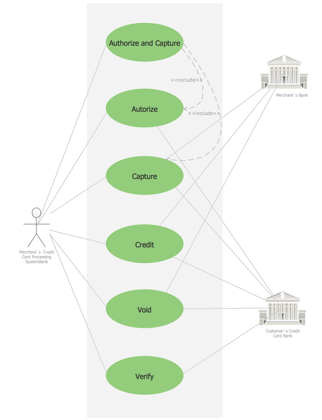
Credit Card Processing System UML Diagram
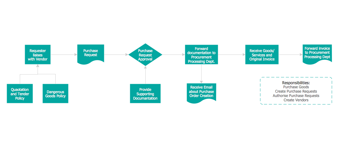
Credit Card Order Process Flowchart. Flowchart Examples
Diagramming Software for Design UML Communication Diagrams

UML Flowchart Symbols

Flowchart Definition

UML Diagram

- System Flowchart For Online Bookshop
- Collaboration Diagram For Bug Tracking System
- UML Collaboration Diagram (UML2.0) | Basic Flowchart Symbols ...
- Data Flow Diagram Of Collaborative System
- UML Collaboration Diagram (UML2.0) | Process Flow Chart Symbol ...
- E Book Management System Collaboration Diagram
- Collaboration Diagram Of Bug Tracking System
- Enterprise Collaboration System Block Diagram
- System Flowchart For Online Shopping Pdf
- Bug Tracking System Project Collaboration Diagram