How To use House Electrical Plan Software


Flowchart Software


Cisco Multimedia, Voice, Phone. Cisco icons, shapes, stencils and symbols
")
Electrical Symbols — Integrated Circuit

Cisco Network Topology. Cisco icons, shapes, stencils and symbols
")
Process Flowchart


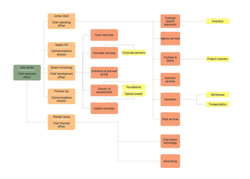
Horizontal Orgchart
Mechanical Drawing Symbols

Accounting Flowchart Symbols

Flowchart Examples and Templates

Process Flow Diagram

Swim Lane Flowchart Symbols

ConceptDraw PRO Compatibility with MS Visio

This electrical floor plan sample shows the lighting and switch layout.
"In building wiring, a light switch is a switch, most commonly used to operate electric lights, permanently connected equipment, or electrical outlets. Portable lamps such as table lamps will have a light switch mounted on the socket, base, or in-line with the cord. Manually operated on/ off switches may be substituted by remote control switches, or light dimmers that allow controlling the brightness of lamps as well as turning them on or off. Light switches are also found in flashlights and automobiles and other vehicles." [Light switch. Wikipedia]
The electrical floor plan example "Lighting and switch layout" was created using the ConceptDraw PRO diagramming and vector drawing software extended with the Electric and Telecom Plans solution from the Building plans area of ConceptDraw Solution Park.
Electrical floor plan

Network Glossary Definition


- How To use House Electrical Plan Software | Design elements ...
- Lighting and switch layout | Lighting and switch layout | Electrical ...
- Lighting and switch layout | How To use House Electrical Plan ...
- Structure Building Plan With Electrical Symbols On It
- Symbols Of Walls
- Electrical Symbols , Electrical Diagram Symbols | How To use House ...
- Electrical Symbols , Electrical Diagram Symbols | How To use House ...
- How To use House Electrical Plan Software | Design elements ...
- How To use House Electrical Plan Software | Value Stream Mapping ...
- How To use House Electrical Plan Software | Interior Design Piping ...
- How To use House Electrical Plan Software | How To use Electrical ...
- How To use House Electrical Plan Software | Lighting and switch ...
- How To use House Electrical Plan Software | Design elements ...
- Power socket outlet layout | How To use House Electrical Plan ...
- How To use House Electrical Plan Software | Design elements ...
- Electrical Diagram Symbols | How To use House Electrical Plan ...
- How To use House Electrical Plan Software | Interior Design Piping ...
- How To use House Electrical Plan Software | Lighting and switch ...
- How To use House Electrical Plan Software | Basic Flowchart ...