Interior Design. Site Plan — Design Elements

Fault Tree Analysis Software

 Class Hierarchy Tree
Class Hierarchy Tree solution enhances the ConceptDraw DIAGRAM and ConceptDraw MINDMAP software functionalities with a wide collection of samples and a large set of pre-made vector shapes, smart and direct connectors allowing all IT and web specialists, web-designers, web-programmers, and lecturers to design the Class Hierarchy Trees and Class Diagrams, object oriented classes, making easier the object oriented programming, illustrating the object oriented programming concepts, the generalization and inheritance in Java class and Python class, as well as designing the Class Hierarchy Mind Maps and autogenerating them in Class Tree Diagrams in ConceptDraw DIAGRAM files.
The FTA diagram sample "Fault tree analysis - Insulin delivery system" was redesigned from the illustration of "CMSI 641: Introduction to Software Engineering. Design of Critical Systems. B.J. Johnson. 2005. Loyola Marymount University".
"Another way of assessing hazards is using fault tree analysis. In this process, each of the identified hazards is covered by a detailed analysis to find out what might cause it. Either inductive or deductive reasoning is applied. In the case of software hazards, the usual focus is to determine faults that will cause the system to fail to deliver a system service, such as a monitoring system. A "fault tree" is constructed to link all the possible situations together, to help identify the interrelationships of the failures, which modules may cause them, and what "trickle-down effects" there might be. Here is an example of a fault tree, as applied to the Insulin delivery system from Sommerville...
Note that this tree is only partially complete, since only the potential software faults are shown on the diagram. The potential failures involving hardware, such as low battery, blood monitor or sensor failure, patient over-exertion or inattention, or medical staff failure are noticeable by their absence.
The fault tree and safety specification processes are two ways of helping with system risk assessment tasks. Once the risks are identified, there are other assessments that need to take place. First, the likelihood of the risk occurrance must be assessed. This is often quantifiable, so numbers may be assigned based on things like MTBF, latency effects, and other known entities. There may be other non-quantifiable contributors to the risk likelihood, however, such that these must be assessed and estimated by experts in the domain. (Don't short-change this process when dealing with critical systems!) Finally, the risk assessment must include the severity of the risk, meaning an estimation of the cost to the project in the event the risk item actually does occur. "Cost to the project" means all associated costs, including schedule delays, human injury, damage to hardware, corruption of data, and so on."
[myweb.lmu.edu/ bjohnson/ cmsi641web/ week15-2.html]
The FTA diagram example "Fault tree analysis - Insulin delivery system" was created using the ConceptDraw PRO diagramming and vector drawing software extended with the Fault Tree Analysis Diagrams solution from the Engineering area of ConceptDraw Solution Park.
FTA diagram

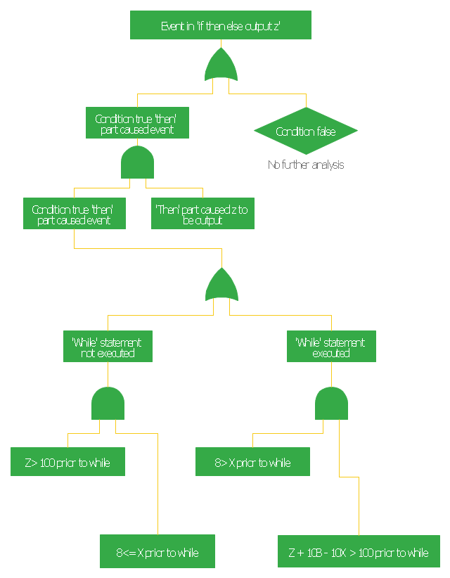
This FTA diagram example was redesigned from the Wikipedia Commons file: Example Code Fault Tree.jpg. [commons.wikimedia.org/ wiki/ File:Example_ Code_ Fault_ Tree.jpg]
"Use of Software Fault Tree Analysis.
Any SFTA must be preceded by a hazard analysis of the entire system. The information in the hazard analysis identifies those undesired events in the system that can cause serious consequences. It should be noted that in comple x systems not all hazards can be predetermined.
In this respect the technique does not claim to produce consistent results irrespective of the analyst. It is dependent on the judgment of the individual as to when to stop the process and which hazards to analyze.
The SFTA can be used at different stages of the software life cycle, beginning at the software requirements phase. At that early stage, only the bare minimum of the software will be defined, though the system will usually have a preliminary design. Only a very high-level SFTA will be able to be performed. However, as the software design progresses, and the code is developed, the SFTA can be “fleshed out” with the new information. High-level blocks can be broken down into specific components (modules, classes, methods, etc.)." [NASA Software Safety Guidebook. hq.nasa.gov/ office/ codeq/ doctree/ 871913.pdf]
The FTA diagram example "Code fault tree" was created using the ConceptDraw PRO diagramming and vector drawing software extended with the Fault Tree Analysis Diagrams solution from the Engineering area of ConceptDraw Solution Park.
Fault tree diagram
PROBLEM ANALYSIS. Root Cause Analysis Tree Diagram


The vector stencils library "Fault tree analysis diagrams" contains 12 symbols for drawing Fault Tree Analysis (FTA) diagrams.
"Fault tree analysis (FTA) is a top down, deductive failure analysis in which an undesired state of a system is analyzed using Boolean logic to combine a series of lower-level events. This analysis method is mainly used in the fields of safety engineering and reliability engineering to understand how systems can fail, to identify the best ways to reduce risk or to determine (or get a feeling for) event rates of a safety accident or a particular system level (functional) failure. FTA is used in the aerospace, nuclear power, chemical and process, pharmaceutical, petrochemical and other high-hazard industries; but is also used in fields as diverse as risk factor identification relating to social service system failure.
In aerospace, the more general term "system Failure Condition" is used for the "undesired state" / Top event of the fault tree. These conditions are classified by the severity of their effects. The most severe conditions require the most extensive fault tree analysis. These "system Failure Conditions" and their classification are often previously determined in the functional Hazard analysis." [Fault tree analysis. Wikipedia]
The shapes example "Fault tree analysis diagrams" was created using the ConceptDraw PRO diagramming and vector drawing software extended with the Fault Tree Analysis Diagrams solution from the Engineering area of ConceptDraw Solution Park.
FTA diagram symbols

 Software Development Area
Solutions from the Software Development Area of ConceptDraw Solution Park collect templates, samples and libraries of vector stencils for drawing the software engineering diagrams and user interface design prototypes.
 DOM Tree
DOM Tree solution extends the functionality of ConceptDraw DIAGRAM and ConceptDraw MINDMAP software making them ideal for designing the Document Object Model, DOM hierarchy and DOM tree diagram. You are free to choose — design your DOM document object model in ConceptDraw DIAGRAM or create the DOM Tree Mind Map in ConceptDraw MINDMAP and then automatically generate it to DOM tree diagram in ConceptDraw DIAGRAM file. This solution includes a lot of samples and predesigned vector shapes, smart and direct connectors for fast and easy drawing strict, informative and professional-looking DOM model, DOM trees, DOM hierarchies, DOM document structures, and DOM Tree Mind Maps.
Interior Design. Storage and Distribution — Design Elements

Fault Tree Analysis Example

ConceptDraw Arrows10 Technology

 Fault Tree Analysis Diagrams
This solution extends ConceptDraw DIAGRAM.5 or later with templates, fault tree analysis example, samples and a library of vector design elements for drawing FTA diagrams (or negative analytical trees), cause and effect diagrams and fault tree diagrams.
 Jackson Structured Programming (JSP) Diagrams
The Jackson Structured Programming (JSP) Diagram solution extends the functionality and drawing abilities of the ConceptDraw DIAGRAM software with set of illustrative JSP diagrams samples and large variety of predesigned vector objects of actions, processes, procedures, selection, iteration, as well as arrows and connectors to join the objects during Jackson structured development and designing Jackson structured programming diagrams, JSP diagram, Jackson structure diagram (JSD), Program structure diagram. The powerful abilities of this solution make the ConceptDraw DIAGRAM ideal assistant for programmers, software developers, structural programmers, computer engineers, applications constructors, designers, specialists in structured programming and Jackson systems design, and other technical, computer and software specialists.
Graphics Software for Business

Root Cause Tree Diagram

Fault Tree Diagram

Project —Task Trees and Dependencies

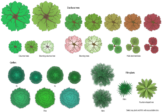
The vector stencils library "Transparent trees" contains 26 clipart images of ornamental trees. Use it to create your landscape design and garden plans.
"Trees create a visual impact in the same way as do other landscape features and give a sense of maturity and permanence to park and garden. They are grown for the beauty of their forms, their foliage, flowers, fruit and bark and their siting is of major importance in creating a landscape. They can be grouped informally, often surrounded by plantings of bulbs, laid out in stately avenues or used as specimen trees. As living things, their appearance changes with the season and from year to year." [Tree. Wikipedia]
The ornamental trees clipart example "Design elements - Transparent trees" was created using the ConceptDraw PRO diagramming and vector drawing software extended with the Landscape & Garden solution from the Building Plans area of ConceptDraw Solution Park.
Ornamental trees
- Data structure diagram with ConceptDraw DIAGRAM | Fault tree ...
- Decision Making | Fault Tree Analysis Software | Influence Diagram ...
- Audit failure - Fault tree analysis diagram | Root cause analysis tree ...
- Fault Tree Analysis Examples And Solutions
- Mechanical Engineering Tree Diagram
- Fault Tree Diagram | Decision Tree Diagram Software Engineering
- FTA diagram - Hazard analysis | How to Create a Fault Tree ...
- Fault Tree Diagram | Fault Tree Analysis Software | Fault Tree ...
- Fault Tree Analysis Software | Design elements - Fault tree analysis ...
- Design elements - Fault tree analysis diagrams | Fta Draw Software