Entity Relationship Diagram Examples


Entity Relationship Diagram Symbols

ERD Symbols and Meanings

UML Class Diagram Generalization Example UML Diagrams

Flowchart Components

Piping and Instrumentation Diagram Software

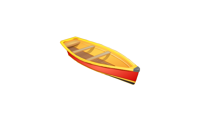
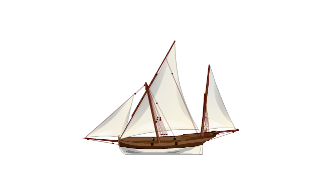
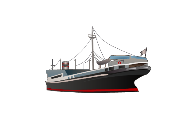
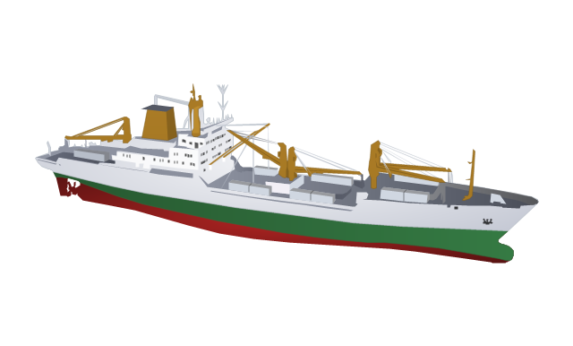
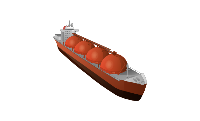
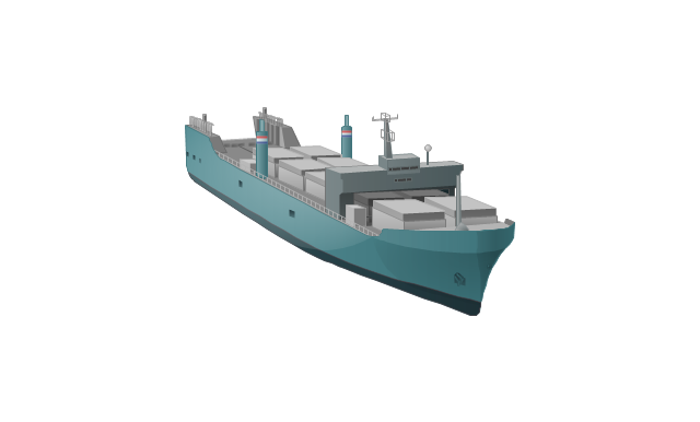
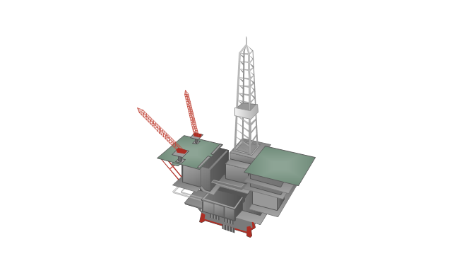
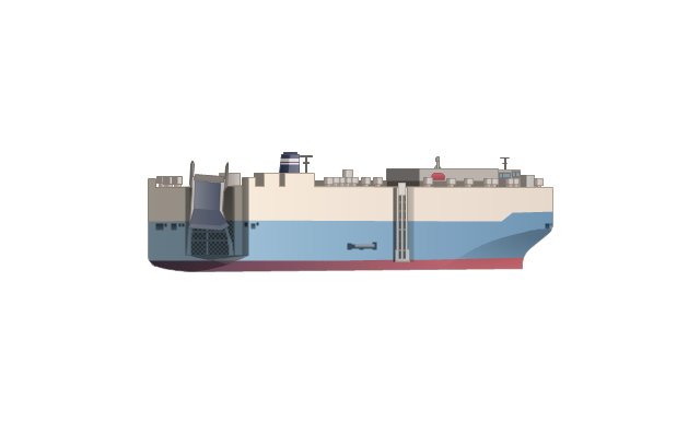
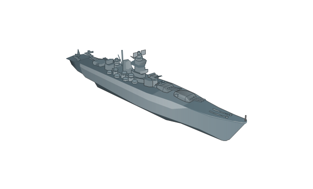
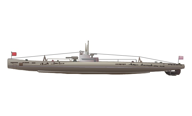
The vector stencils library "Watercraft" contains 28 clip art images for creating ship transport illustrations, presentation slides, infographics and webpages using the ConceptDraw PRO diagramming and vector drawing software.
"The term watercraft covers a range of different vehicles including ships, boats, hovercraft and submarines, and differs from a simple device that merely floats, such as a log raft. ...
Usually the purposes behind watercraft designs and skills are for seafaring education or leisure activities, fishing and resource extraction, transportation of cargo or passengers, and for conducting combat or salvage operations. In general, the purpose of a water vehicle identifies its utility with a maritime industry sub-sector." [Watercraft. Wikipedia]
The vector stencils library "Watercraft" is included in the Aerospace and Transport solution from the Illustrations area of ConceptDraw Solution Park.
www.conceptdraw.com/ solution-park/ illustrations-aerospace-transport
Boat
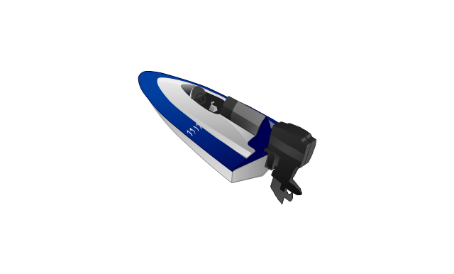
Motorboat
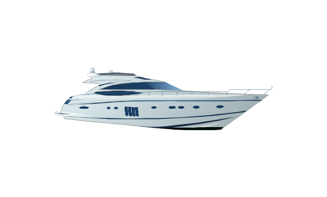
Yacht
Sailing yacht

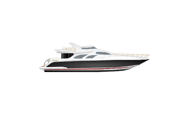
Motor yacht
Passenger vessel

Sailing ship
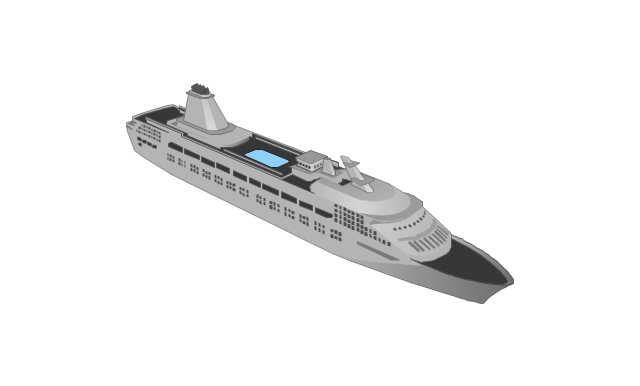
Passenger ship
Regular ship
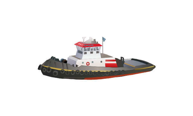
Tugboat
Oil ship
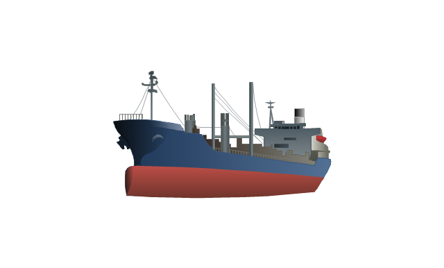
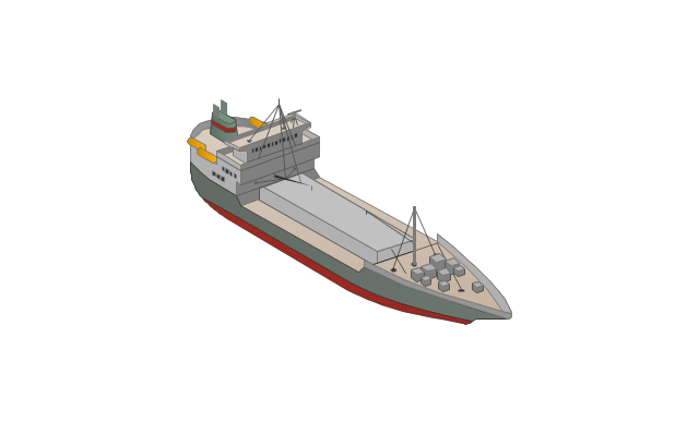
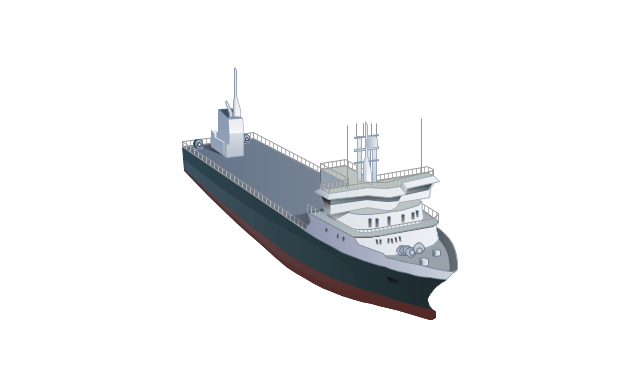
Dry cargo ship
Dry cargo vessel
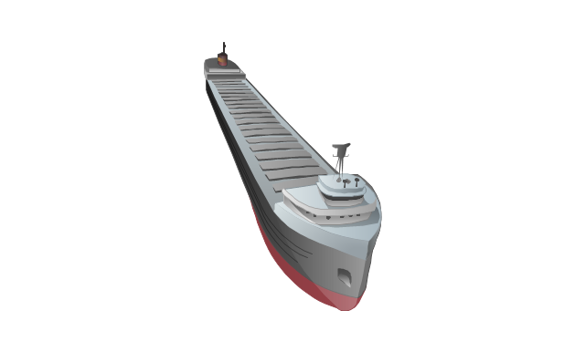
Capesize bulk-carrier
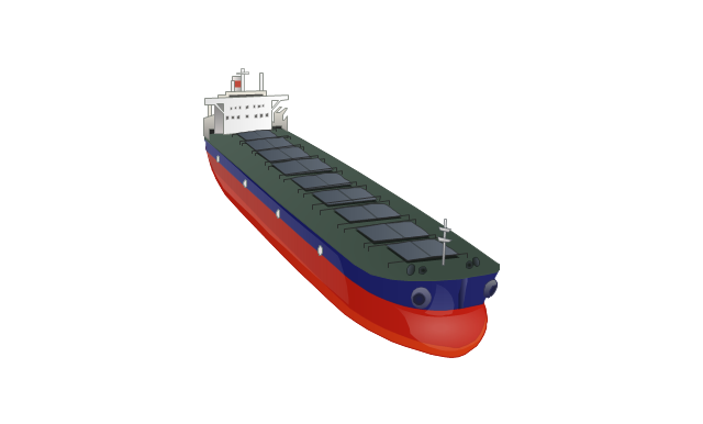
Handysize bulk-carrier
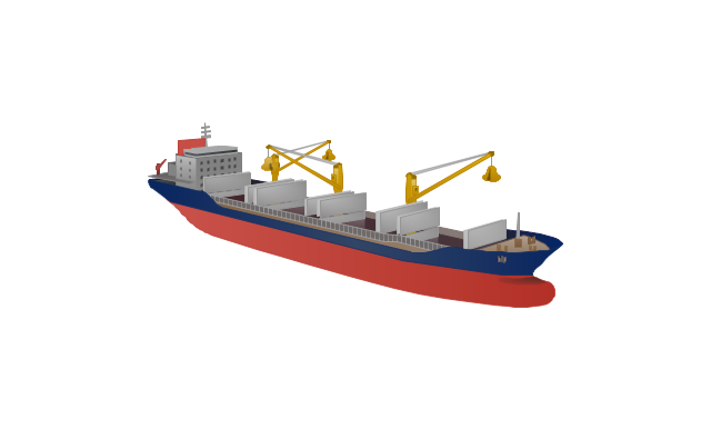
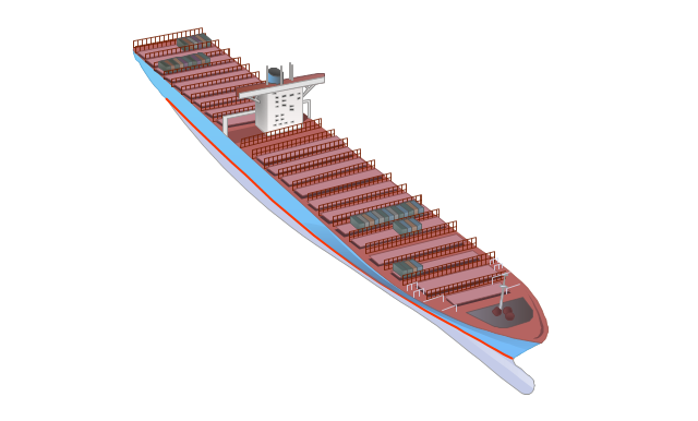
Container ship
Multipurpose ship
Reefer
Oil tanker

Reefer vessel
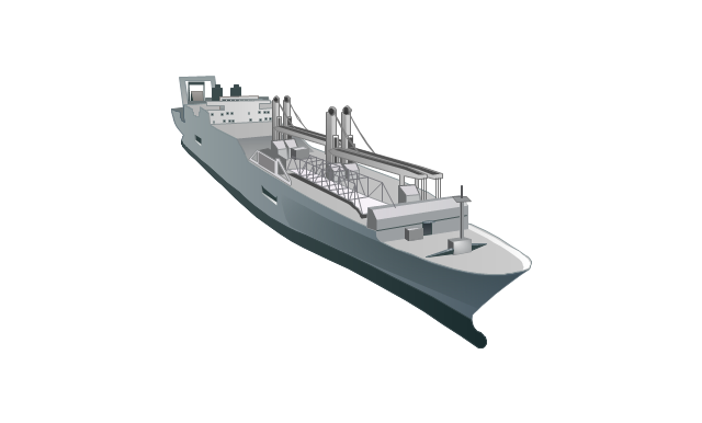
Gas ship
Lighter aboard ship
Offshore oil platform
Car carrier
Battleship
Submarine
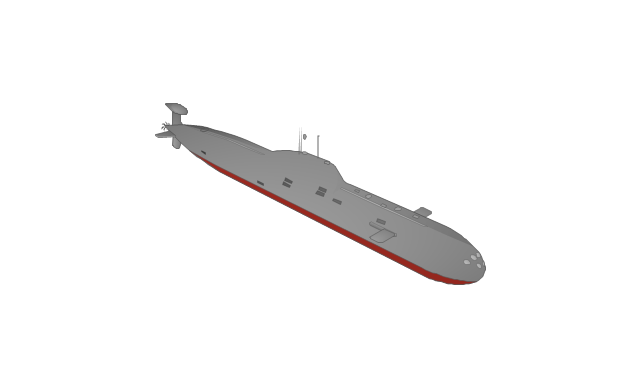
Submarine
Container ship
Components of ER Diagram

 Telecommunication Network Diagrams
Telecommunication Network Diagrams solution extends ConceptDraw DIAGRAM software with samples, templates, and great collection of vector stencils to help the specialists in a field of networks and telecommunications, as well as other users to create Computer systems networking and Telecommunication network diagrams for various fields, to organize the work of call centers, to design the GPRS networks and GPS navigational systems, mobile, satellite and hybrid communication networks, to construct the mobile TV networks and wireless broadband networks.
Active Directory Diagram

- Simple Ship Line Drawing
- Draw And Label A Simple Ship Board Distribution System
- A Simple Drawing Of A Water Transportation
- Draw And Lebal The Ship
- Draw And Lebel A Simple Ship Board Distribution System
- Draw And Label A Ship Board Distrubution System
- Simple Boat Illustration Png
- Draw And Label A Ship
- Draw Passenger Ship And Label
- Ship Vector Symbol Simple