Business Processes description with ConceptDraw PRO

This IDEF3 symbols example was redesigned from the Wikimedia Commons file: 3-01a Symbols Used for IDEF3 Process Description Schematics.jpg.
[commons.wikimedia.org/ wiki/ File:3-01a_ Symbols_ Used_ for_ IDEF3_ Process_ Description_ Schematics.jpg]
"Process schematics tend to be the most familiar and broadly used component of the IDEF3 method. These schematics provide a visualization mechanism for process-centered descriptions of a scenario. The graphical elements that comprise process schematics include Unit of Behavior (UOB) boxes, precedence links, junctions, referents, and notes. Referents and notes are constructs that are common across process and object schematics. Each of the graphical elements used for developing process schematics is presented below, together with discussions of how to formulate more complex statements using those graphical elements. The discussion begins with the most fundamental of these building blocks: the UOB." [IDEF3 Process Description Capture Method Report AL-TR-1995-XXXX. idef.com/ pdf/ Idef3_ fn.pdf]
The sample "Symbols used for IDEF3 process description schematics" was created using the ConceptDraw PRO diagramming and vector drawing software extended with the solution "IDEF Business Process Diagrams" from the area "Business Processes" of ConceptDraw Solution Park.
IDEF3 diagram symbols
Basic Flowchart Symbols and Meaning


 IDEF Business Process Diagrams
Use the IDEF Business Process Diagrams solution to create effective database designs and object-oriented designs, following the integration definition methodology.
The vector stencils library "Process annotations" contains 22 symbols of interface points, slope, off-sheet labels, callouts and textboxes.
Use these shapes for setting automatic labels to display a datasheet field for a pipeline shape, labels, captions, outlines, off-sheet labels, text balloons, annotations, outlines, tags, and descriptions.
"In engineering a process is a set of interrelated tasks that, together, transform inputs into outputs. These tasks may be carried out by people, nature, or machines using resources; so an engineering process must be considered in the context of the agents carrying out the tasks, and the resource attributes involved. Systems Engineering normative documents and those related to Maturity Models are typically based on processes. For example, System Engineering processes of the EIA-632 and processes involved in the Capability Maturity Model Integration (CMMI) institutionalization and improvement approach. Constraints imposed on the tasks and resources required to implement them are essential for executing the tasks mentioned.
A chemical process is a series of unit operations used to produce a material in large quantities.
In the chemical industry, chemical engineers will use the following to define or illustrate a process:
Process Flow Diagram (PFD),
Piping and instrumentation diagram
(P&ID),
Simplified process description,
Detailed process description,
Project management,
Process simulation." [Process (engineering). Wikipedia]
The example "Design elements - Process annotations" was created using the ConceptDraw PRO diagramming and vector drawing software extended with the Chemical and Process Engineering solution from the Engineering area of ConceptDraw Solution Park.
Process annotation symbols

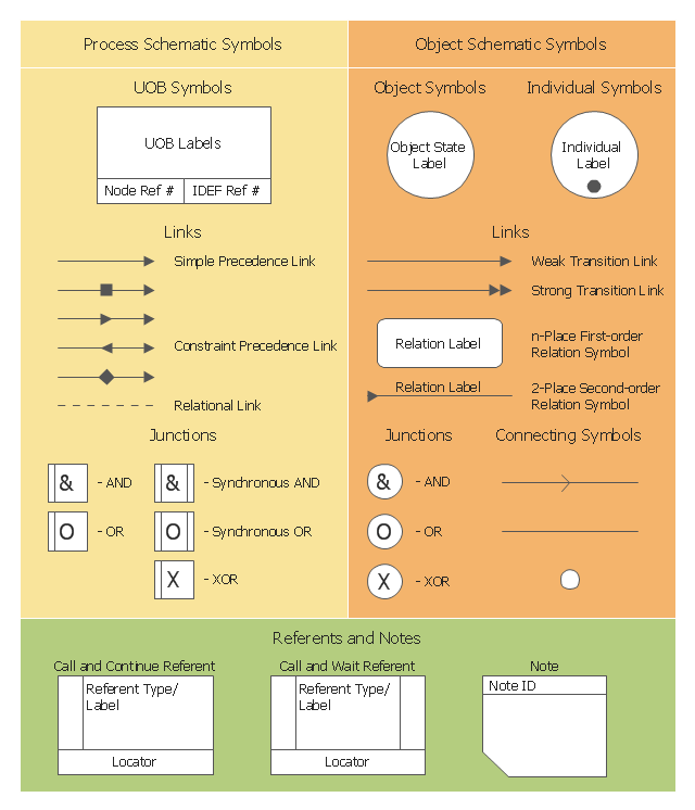
The vector stencils library "IDEF3 process schematic symbols" contains 12 shapes: unit of behavior (UOB), links, junctions, .
Use it to design your IDEF3 process schematic diagrams.
"Process schematics tend to be the most familiar and broadly used component of the IDEF3 method. These schematics provide a visualization mechanism for processcentered descriptions of a scenario. The graphical elements that comprise process schematics include Unit of Behavior (UOB) boxes, precedence links, junctions, referents, and notes. The building blocks here are:
- Unit of Behavior (UOB) boxes.
- Links: Links are the glue that connect UOB boxes to form representations of dynamic processes.
- Simple Precedence Links: Precedence links express temporal precedence relations between instances of one UOB and those of another.
- Activation Plots: Activation plots are used to represent activations.
- Dashed Links: Dashed links carry no predefined semantics.
- Link Numbers: All links have an elaboration and unique link numbers.
Activation Semantics for Nonbranching Process Schematics.
- Junctions: Junctions in IDEF3 provide a mechanism to specify the logic of process branching.
- UOB Decompositions: Elaborations capture and structure detailed knowledge about processes.
- UOB Reference Numbering Scheme: A UOB box number is assigned to each UOB box in an IDEF3 Process Description.
- Partial Descriptions: UOB boxes are joined together by links. Because of the description capture focus of IDEF3, it is possible to conceive of UOBs without links to other parts of an IDEF3 schematic.
- Referents: Referents enhance understanding, provide additional meaning, and simplify the construction (i.e., minimize clutter) of both process schematics and object schematics." [IDEF3. Wikipedia]
The shapes example "Design elements - IDEF3 process schematic symbols" was created using the ConceptDraw PRO diagramming and vector drawing software extended with the solution "IDEF Business Process Diagrams" from the area "Business Processes" of ConceptDraw Solution Park.
IDEF3 business process diagram

Process Flowchart


IDEF3 Standard

Flow chart Example. Warehouse Flowchart


The Best Business Process Modeling Software


Business Process Reengineering Examples

An Event-driven Process Chain (EPC) - flowchart used for business process modelling
 flowchart used for business process modelling")
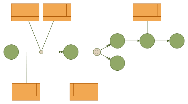
This IDEF3 diagram example was redesigned from the Wikimedia Commons file: 6-4 Example IDEF3 Object State Transition Schematic.jpg.
[commons.wikimedia.org/ wiki/ File:6-4_ Example_ IDEF3_ Object_ State_ Transition_ Schematic.jpg]
"Quick Reading of IDEF3 Process Descriptions: An Example.
An example approach for reading a schematic is described in the following steps. This outline for reading a schematic would be repeated, with few modifications, for all decompositions, whether found in a Process Schematic or an Object Schematic. In general, decompositions are read after the parent schematic has been read and understood.
The Big Picture.
A crucial step in the description-reading process is to understand the big picture
relevant to the real-life situation described. This big picture can be gained by reading and understanding the statement of purpose, statement of scope, objective of the scenario being described, and viewpoint of the IDEF3 Process Description. ...
Scan the Schematic.
Readers should become familiar with the scenario by scanning the schematic from left to right. This involves becoming familiar with the individual elements (e.g., UOBs, links, and junctions) displayed in the schematic. This is not an in-depth study of the schematic; rather, it provides readers with a general impression of the process being described and an overall understanding of the logic flow in the scenario.
Understand the Description.
In this step, readers gain a detailed understanding of the schematic associated with a scenario, object, or a decomposition of a schematic element. This is the part of the communication process that is most individualized and requires the most time. It is helpful to partition the schematic into understandable pieces." [IDEF3 Process Description Capture Method Report AL-TR-1995-XXXX. idef.com/ pdf/ Idef3_ fn.pdf]
The diagram sample "IDEF3 object state transition schematic" was created using the ConceptDraw PRO diagramming and vector drawing software extended with the solution "IDEF Business Process Diagrams" from the area "Business Processes" of ConceptDraw Solution Park.
IDEF3 business process diagram
Total Quality Management with ConceptDraw
 method - Fishbone diagram template")
Types of Flowcharts


- Process Flowchart | Symbols used for IDEF3 process description ...
- Symbols used for IDEF3 process description schematics
- Description Of Process Flow Instrumentation Diagram
- Management | Business Productivity Area | Business Processes ...
- Data Flow Diagram | Flowcharts | Business Processes description ...
- Process Flowchart | Plant Layout Plans | Flowchart Definition ...
- Business Processes description with ConceptDraw PRO | Flow ...
- Business Processes description with ConceptDraw PRO | Types of ...
- Business Process Optimization | Business Processes description ...
- BPR Diagram. Business Process Reengineering Example ...
- Business Processes description with ConceptDraw PRO | Diagram ...
- Chemical and Process Engineering | Process Engineering | How to ...
- Program Evaluation and Review Technique (PERT) with ...
- Basic Flowchart Symbols and Meaning | Process Flowchart ...
- Total Quality Management TQM Diagrams | Process Flowchart ...
- Process Flowchart | Business diagrams & Org Charts with ...
- Flowchart Definition | Basic Flowchart Symbols and Meaning | Cross ...
- Basic Flowchart Symbols and Meaning | Process Flowchart | Flow ...
- Business Process Reengineering Examples | BPR Diagram ...
- How to Draw a Chemical Process Flow Diagram | Chemical and ...