Cisco Routers. Cisco icons, shapes, stencils and symbols

"A computer network or data network is a telecommunications network that allows computers to exchange data. In computer networks, networked computing devices (network nodes) pass data to each other along data connections. The connections (network links) between nodes are established using either cable media or wireless media. The best-known computer network is the Internet.
Network devices that originate, route and terminate the data are called network nodes. Nodes can include hosts such as servers and personal computers, as well as networking hardware. Two devices are said to be networked when a device is able to exchange information with another device." [Computer network. Wikipedia]
This computer communication network diagram example was created using the ConceptDraw PRO diagramming and vector drawing software extended with the Computer and Networks solution from the Computer and Networks area of ConceptDraw Solution Park.
Network diagram

Network Gateway Router


Hotel Network Topology Diagram. Hotel Guesthouse WiFi Network

Network Security Devices

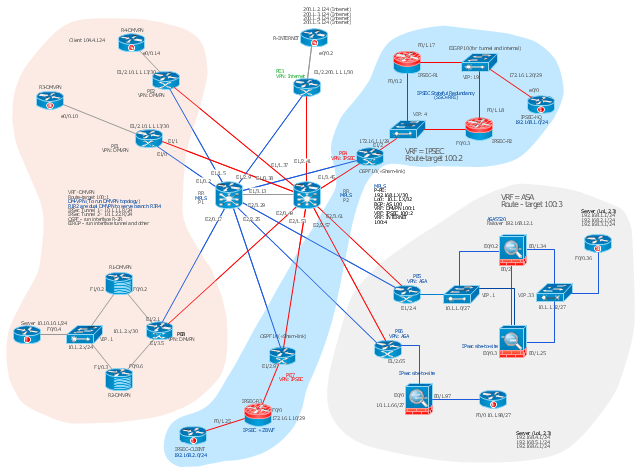
This Cisco network diagram example was drawn on the base of the figure illustrating the post "Cisco Lab 1 : Network Design from the requirement" from the blog "Thai Cisco Club".
"1. Core service porvider by assign P router as P1 and P2, PE router as PE1 - 8 for support CE router of customers.
2. From 1st customer project, assign R1-DMVPN and R2-DWVPN as DMVPN Hub, and R3-DMVPN and R4-DMVPN as DMVPN-Spoke that on different site.
3. From 2nd customer project, assign IP-SEC R1 and IP-SEC R2 as SSO-IP-SEC Router on HQ site, and IP-SEC R3 as branch site that far away."
[thai-cisco-club.blogspot.com/ 2011/ 10/ cisco-lab-1-network-design-from.html]
The diagram example "Cisco network design from the requirement" was created using the ConceptDraw PRO diagramming and vector drawing software extended with the Cisco Network Diagrams solution from the Computer and Networks area of ConceptDraw Solution Park.
Cisco network diagram
"... logical topology shows how data flows within a network, regardless of its physical design. ...
... mapping the data flow between the components determines the logical topology of the network." [Network topology. Wikipedia]
"In a shared media topology, all the systems have the ability to access the physical layout whenever they need it. The main advantage in a shared media topology is that the systems have unrestricted access to the physical media. Of course, the main disadvantage to this topology is collisions. If two systems send information out on the wire at the same time, the packets collide and kill both packets. Ethernet is an example of a shared media topology. ...
The token-based topology works by using a token to provide access to the physical media. In a token-based network, there is a token that travels around the network. When a system needs to send out packets, it grabs the token off of the wire, attaches it to the packets that are sent, and sends it back out on the wire. As the token travels around the network, each system examines the token. When the packets arrive at the destination systems, those systems copy the information off of the wire and the token continues its journey until it gets back to the sender. When the sender receives the token back, it pulls the token off of the wire and sends out a new empty token to be used by the next machine." [Logical topology. Wikipedia]
This Cisco logical computer network diagram example was created using the ConceptDraw PRO diagramming and vector drawing software extended with the Cisco Network Diagrams solution from the Computer and Networks area of ConceptDraw Solution Park.
Logical network diagram
This Cisco network diagram example was drawn on the base of the figure illustrating the post "Cisco Lab 1 : Network Design from the requirement" from the blog "Thai Cisco Club".
"1. Core service porvider by assign P router as P1 and P2, PE router as PE1 - 8 for support CE router of customers.
2. From 1st customer project, assign R1-DMVPN and R2-DWVPN as DMVPN Hub, and R3-DMVPN and R4-DMVPN as DMVPN-Spoke that on different site.
3. From 2nd customer project, assign IP-SEC R1 and IP-SEC R2 as SSO-IP-SEC Router on HQ site, and IP-SEC R3 as branch site that far away."
[thai-cisco-club.blogspot.com/ 2011/ 10/ cisco-lab-1-network-design-from.html]
The diagram example "Cisco network design from the requirement" was created using the ConceptDraw PRO diagramming and vector drawing software extended with the Cisco Network Diagrams solution from the Computer and Networks area of ConceptDraw Solution Park.
"1. Core service porvider by assign P router as P1 and P2, PE router as PE1 - 8 for support CE router of customers.
2. From 1st customer project, assign R1-DMVPN and R2-DWVPN as DMVPN Hub, and R3-DMVPN and R4-DMVPN as DMVPN-Spoke that on different site.
3. From 2nd customer project, assign IP-SEC R1 and IP-SEC R2 as SSO-IP-SEC Router on HQ site, and IP-SEC R3 as branch site that far away."
[thai-cisco-club.blogspot.com/ 2011/ 10/ cisco-lab-1-network-design-from.html]
The diagram example "Cisco network design from the requirement" was created using the ConceptDraw PRO diagramming and vector drawing software extended with the Cisco Network Diagrams solution from the Computer and Networks area of ConceptDraw Solution Park.
Cisco network diagram
Network Security

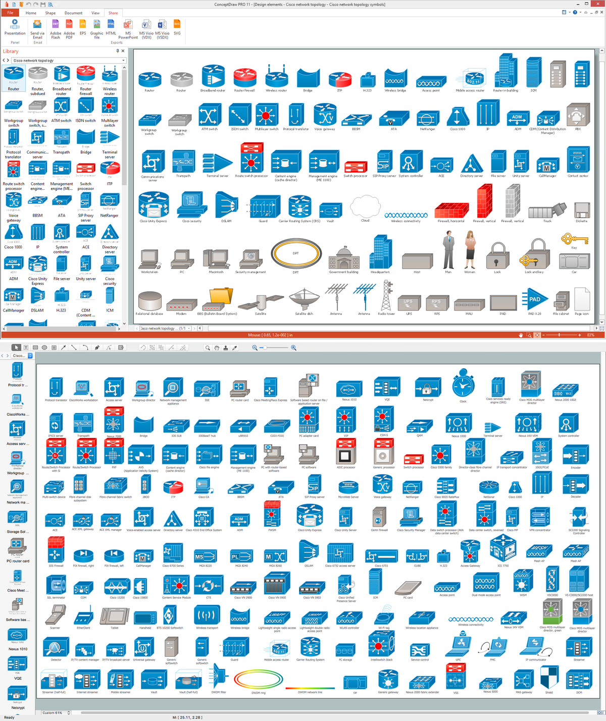
Cisco Products Additional. Cisco icons, shapes, stencils and symbols

Cisco Network Topology. Cisco icons, shapes, stencils and symbols
Local area network (LAN). Computer and Network Examples
 diagram")
Network Hubs

Hotel Network Topology Diagram


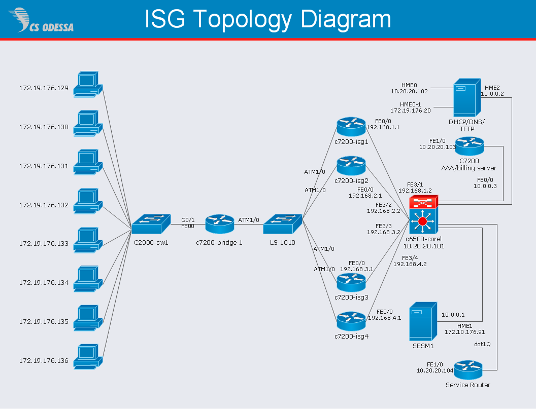
Network Diagram Software ISG Network Diagram
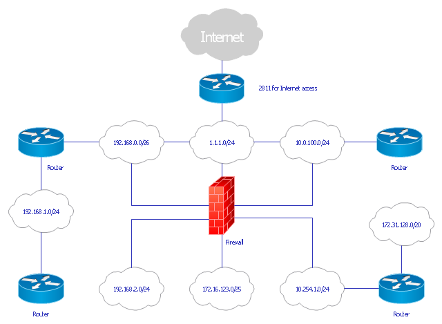
- Network Diagram Including Firewall Server And Router
- How To use Switches in Network Diagram | Communication network ...
- Network Diagram Cloud Firewall Workstation Switch Server
- Network Diagram Including Workstation Switch Server Router
- Network Diagram Sample With Firewall Switch Routers
- Wireless router network diagram | Network Diagram Software Home ...
- Basic Network Diagram With Firewall
- Firewall between LAN and WAN | Network Security Diagrams ...
- Wireless router network diagram | Wireless Network Mode | Cisco ...
- Lan Network Diagram Router Firewall
- Network Diagram Workstation Switch Server Router Firewall And
- Wireless broadband network diagram | Firewall between LAN and ...
- Router Firewall Switch Diagram
- Communication network diagram | ATM Network. Computer and ...
- Cisco Routers . Cisco icons, shapes, stencils and symbols | Wireless ...
- Cisco Routers . Cisco icons, shapes, stencils and symbols | Design ...
- Create Ethernet Basic Network Diagram Using Firewall
- Network Diagram And Workstation Switch Server Router Firewall
- How To use Switches in Network Diagram | Star Network Topology ...