 Cloud Computing Diagrams
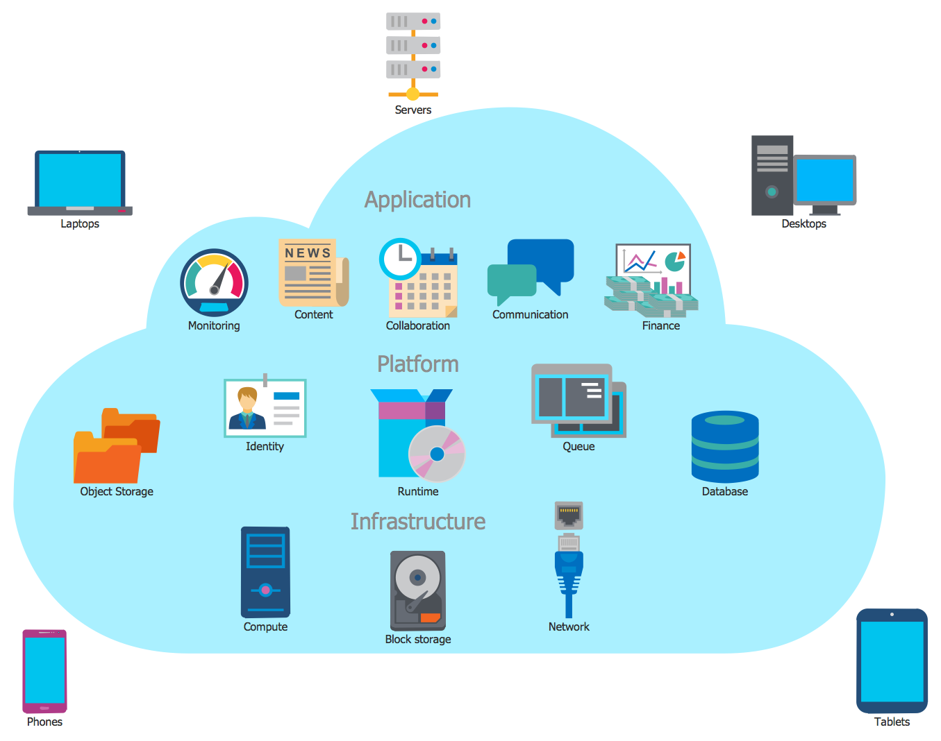
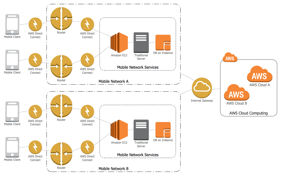
The Cloud Computing Diagrams solution extends the functionality of the ConceptDraw DIAGRAM diagramming software with a comprehensive collection of libraries of commonly accepted cloud computing vector stencils to help you to get started designing Cloud Computing Diagrams, Architecture Diagrams and Cloud Computing Architecture Diagrams without effort. This solution lets one professionally depict the way how the cloud computing works, allows giving a powerful introduction to the Cloud computing architecture and Amazon cloud computing architecture, to display the essence of the cloud computing, the main characteristics and classification of the cloud services thanks to the wide variety of predesigned samples and examples.
Cisco WAN. Cisco icons, shapes, stencils and symbols

Cisco Network Topology. Cisco icons, shapes, stencils and symbols

ER Diagram for Cloud Computing

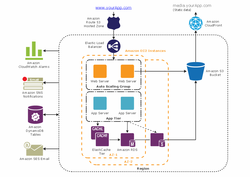
Diagramming tool - Amazon Web Services and Cloud Computing Diagrams
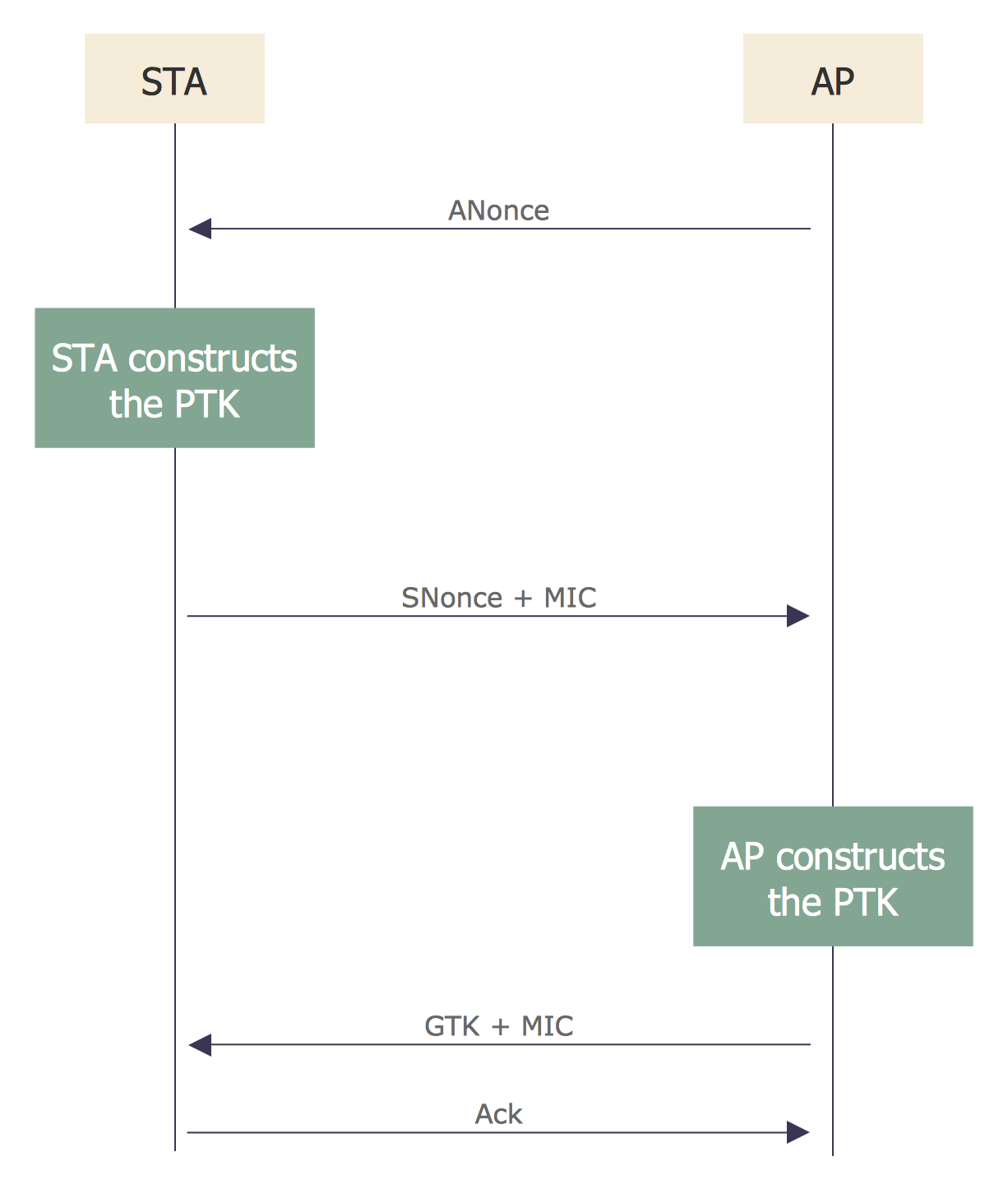
Sequence Diagram for Cloud Computing
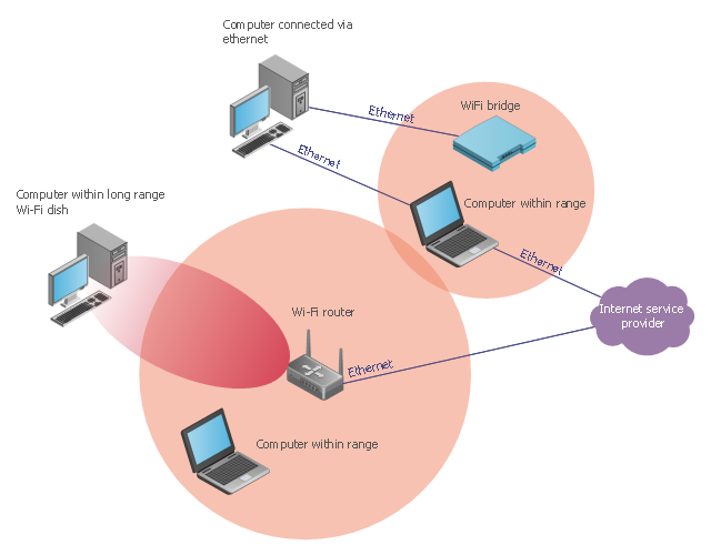
This wireless network diagram sample illustrates long-range Wi-Fi.
"Long-range Wi-Fi is used for low-cost, unregulated point-to-point computer network connections, as an alternative to other fixed wireless, cellular networks or satellite Internet access.
Wi-Fi networks have a range that's limited by the transmission power, antenna type, the location they're used in, and the environment. A typical wireless router in an indoor point-to-multipoint arrangement using 802.11b or 802.11g and a stock antenna might have a range of 32 metres (105 ft). Outdoor point-to-point arrangements, through use of directional antennas, can be extended with many kilometers between stations." [Long-range Wi-Fi. Wikipedia]
The wireless network diagram example "Long-range Wi-Fi" was created using the ConceptDraw PRO diagramming and vector drawing software extended with the Wireless Networks solution from the Computer and Networks area of ConceptDraw Solution Park.
Wireless network diagram
"There are two definitions for wireless LAN roaming:
Internal Roaming (1): The Mobile Station (MS) moves from one access point (AP) to another AP within a home network because the signal strength is too weak. An authentication server (RADIUS) performs the re-authentication of MS via 802.1x (e.g. with PEAP). The billing of QoS is in the home network. A Mobile Station roaming from one access point to another often interrupts the flow of data among the Mobile Station and an application connected to the network. The Mobile Station, for instance, periodically monitors the presence of alternative access points (ones that will provide a better connection). At some point, based on proprietary mechanisms, the Mobile Station decides to re-associate with an access point having a stronger wireless signal. The Mobile Station, however, may lose a connection with an access point before associating with another access point. In order to provide reliable connections with applications, the Mobile Station must generally include software that provides session persistence.
External Roaming (2): The MS (client) moves into a WLAN of another Wireless Internet Service Provider (WISP) and takes their services (Hotspot). The user can independently of his home network use another foreign network, if this is open for visitors. There must be special authentication and billing systems for mobile services in a foreign network." [Wireless LAN. Wikipedia]
This Cisco roaming wireless local area network diagram example was created using the ConceptDraw PRO diagramming and vector drawing software extended with the Cisco Network Diagrams solution from the Computer and Networks area of ConceptDraw Solution Park.
WLAN diagram

Used Solutions
 Network Security Diagrams
The Network Security Diagrams solution presents a large collection of predesigned cybersecurity vector stencils, cliparts, shapes, icons and connectors to help you succeed in designing professional and accurate Network Security Diagrams, Network Security Infographics to share knowledge about effective ways of networks protection with help of software and network security devices of different cyber security degrees, Network Plans for secure wireless network, Computer Security Diagrams to visually tell about amazing possibilities of IT security solutions. The samples and examples reflect the power of ConceptDraw DIAGRAM software in drawing Network Security Diagrams, give the representation about variety of existing types of attacks and threats, help to realize their seriousness and the methods to deal with them.
Network Topologies


How to Build Cloud Computing Diagram Principal Cloud Manufacturing

Cloud Computing Architecture
 AWS Architecture Diagrams
AWS Architecture Diagrams with powerful drawing tools and numerous predesigned Amazon icons and AWS simple icons is the best for creation the AWS Architecture Diagrams, describing the use of Amazon Web Services or Amazon Cloud Services, their application for development and implementation the systems running on the AWS infrastructure. The multifarious samples give you the good understanding of AWS platform, its structure, services, resources and features, wide opportunities, advantages and benefits from their use; solution’s templates are essential and helpful when designing, description and implementing the AWS infrastructure-based systems. Use them in technical documentation, advertising and marketing materials, in specifications, presentation slides, whitepapers, datasheets, posters, etc.
Amazon Cloud
Network Diagram Software Logical Network Diagram


- Cloud Network Diagram
- Wide area network (WAN) topology. Computer and Network Examples
- Cloud Computing Architecture Diagrams | How To Create a MS ...
- Government Cloud | Network Security Diagrams | Network Security ...
- Cloud Computing | Cloud Computing Diagrams | Cloud Computing ...
- Satellite telecom network diagram | How to Build Cloud Computing ...
- Roaming wireless local area network diagram | Fully Connected ...
- Wireless Network WLAN | WLAN | How to Create a Wireless ...
- Mesh Network Topology Diagram | Wireless mesh network diagram ...
- Network Architecture | AWS Architecture Diagrams | Cloud ...
- A Network Diagram That Includes Cloud Computing
- Local Area Network Diagram
- Mesh Network Topology Diagram | Fully Connected Network ...
- Internet Cloud Diagram Of Network Design
- Wireless router network diagram | Computer Network Diagrams ...
- Network Cloud Scheme
- How to Create a Cloud Computing Diagram Using ConceptDraw PRO
- Sequence Diagram for Cloud Computing | Introduction to Cloud ...
- Satellite telecom network diagram | Mobile satellite communication ...
- Wireless router network diagram | Wireless networks - Vector ...