UML Class Diagram. Design Elements

UML Notation

HelpDesk
How to Create a CCTV Diagram

UML Class Diagram Constructor

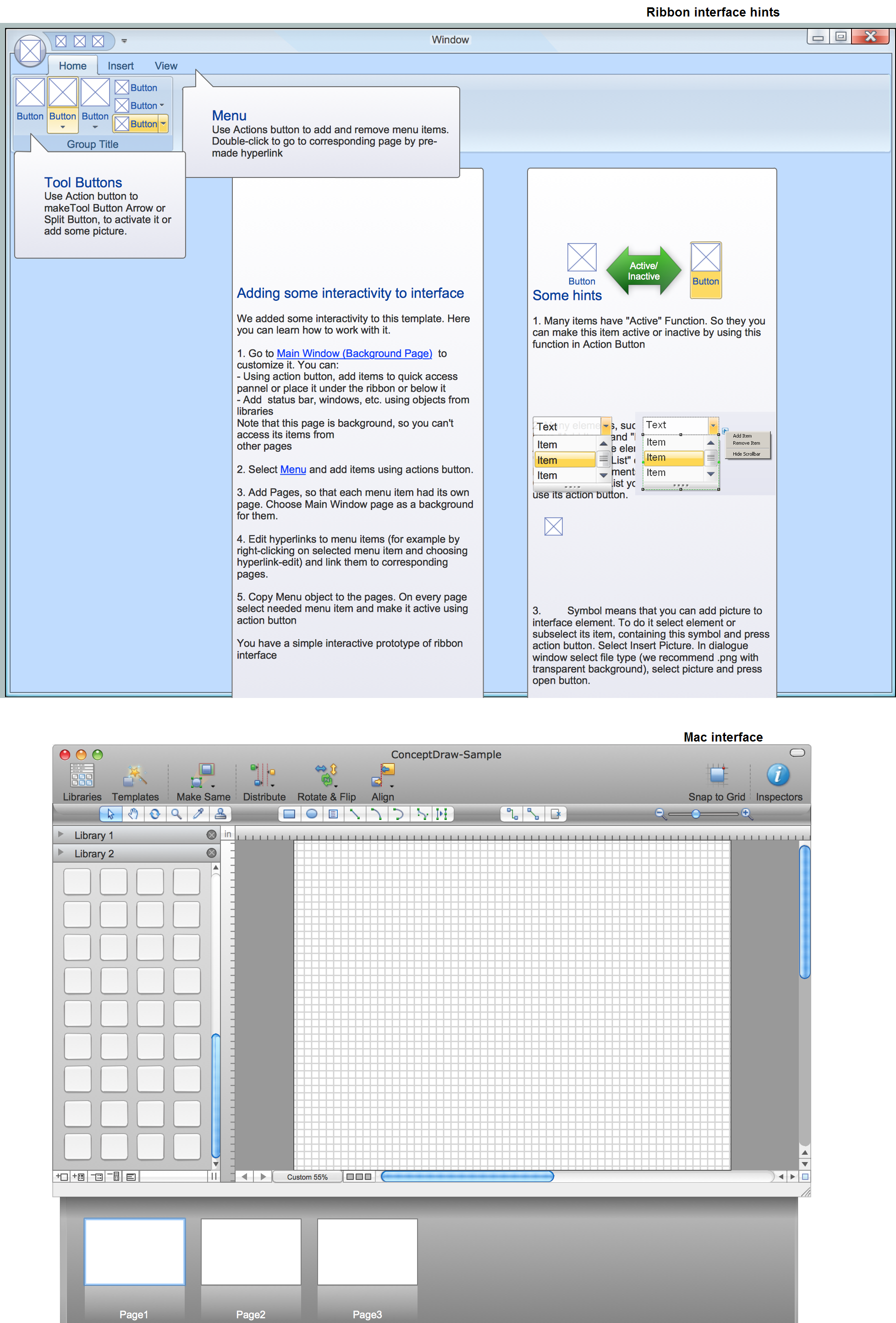
GUI Prototyping with ConceptDraw DIAGRAM
Sales Steps

IDEF4 Standard

Create Floor Plans Easily with ConceptDraw DIAGRAM


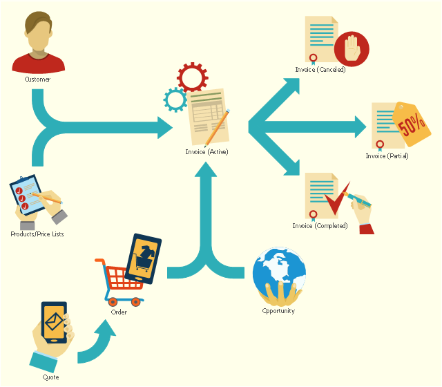
This flowchart example shows the lifecycle of an invoice in Microsoft Dynamics CRM. It was redesigned from the Wikimedia Commons file: Invoice lifecycle.svg. [commons.wikimedia.org/ wiki/ File:Invoice_ lifecycle.svg]
"Microsoft Dynamics CRM is a customer relationship management software package developed by Microsoft. Out of the box, the product focuses mainly on Sales, Marketing, and Service (help desk) sectors...
Dynamics CRM is a server-client application, which, like Microsoft SharePoint, is primarily an IIS-based web application which also supports extensive web services interfaces. Clients access Dynamics CRM either by using a Browser or by a thick client plug-in to Microsoft Outlook." [Microsoft Dynamics CRM. Wikipedia]
The process flowchart example "Invoice lifecycle" was created using the ConceptDraw PRO diagramming and vector drawing software extended with the Sales Flowcharts solution from the Marketing area of ConceptDraw Solution Park.
Lifecycle of an invoice in Microsoft Dynamics CRM
IDEF1X Standard

- Empty Venn Diagram
- Empty Flow Charts
- Invoice lifecycle | Flowchart design. Flowchart symbols, shapes ...
- System Flowchart For Crm
- Marketing - Vector stencils library | Land sales process flowchart ...
- Pyramid Diagram and Pyramid Chart | Circular Flow Diagram ...
- ERD Symbols and Meanings | ER Diagram Styles | Basic Flowchart ...
- Marketing - Vector stencils library | Bull Diagram Need Analysis
- Process Flowchart | Basic Flowchart Symbols and Meaning ...
- Solving quadratic equation algorithm - Flowchart | Basic Flowchart ...
- Target Diagram | ConceptDraw Solution Park | UML Diagram Editor ...
- Data flow diagram (DFD) - Payment for goods using UPS code ...
- Relationship marketing | Venn diagram - Relationship marketing ...
- Target Diagram | How to Create a Sales Flowchart Using ...
- Hand Trucks Diagram
- Cross Functional Flowchart Shapes Stencil | Cross-functional ...
- Process Flowchart - Draw Process Flow Diagrams by Starting with ...
- Audio, Video, Media | Top 5 Android Flow Chart Apps | Tree Network ...
- ERD Symbols and Meanings | Entity Relationship Diagram Symbols ...