This site uses cookies. By continuing to browse the ConceptDraw site you are agreeing to our Use of Site Cookies.
HelpDesk

How to Draw a Circular Arrows Diagram

The cyclic recurrence is a fundamental property of multiple systems. The cycle is a process which consists of elements (phases, stages, stages) following each other. Many processes in astronomy, biology, chemistry, physics, mathematics, etc. have a cycle properties. It is also widely used in information technologies and marketing analysis. Graphical representation of cyclic processes can have many forms. It can be a circle, parabola, hyperbola, ellipse, and others. A Circular Arrows Diagram is used as one of the statistical charts in the business, mass media and marketing. ConceptDraw DIAGRAM provides tools for making easy drawing Circular Arrows Diagrams.

Cloud Computing Architecture Diagrams

For documenting the Cloud Computing Architecture with a goal to facilitate the communication between stakeholders are successfully used the Cloud Computing Architecture diagrams. It is convenient and easy to draw various Cloud Computing Architecture diagrams in ConceptDraw DIAGRAM software with help of tools of the Cloud Computing Diagrams Solution from the Computer and Networks Area of ConceptDraw Solution Park.

Concept Map

A concept map is a way of representing relationships between ideas, images, or words.
How to draw a Concept Map quick, easy and effective? ConceptDraw DIAGRAM offers the unique Concept Maps Solution from the "Diagrams" Area that will help you!
HelpDesk

How to Change the Measurement Units and Drawing Scale

ConceptDraw DIAGRAM enables choosing the most suitable scale and units of measurement with just one click.
There are different units of measurement that can be used for length dimensions. When making scaled drawing we can't keep in mind just meters, centimeters, and millimeters; we also need to remember about yards, feet, and inches. This is because the United States applies its own system of measurement units, while the rest of the world employs metric measurement units. This article explains how you can change the scale and measurement units in a ConceptDraw DIAGRAM drawing.

IDEF0 Visio

ConceptDraw DIAGRAM extended with IDEF0 Diagrams solution from the Software Development area of ConceptDraw Solution Park is a powerful diagramming and vector drawing IDEF0 software. All IDEF0 diagrams created in ConceptDraw DIAGRAM are vector graphic documents and can be reviewed, modified and converted to MS Visio XML format. To obtain the IDEF0 Visio documents from ConceptDraw DIAGRAM documents use the wide export possibilities of ConceptDraw DIAGRAM.
HelpDesk

How to Edit Grouped Objects on PC
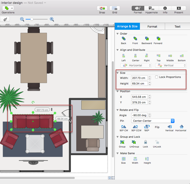
ConceptDraw DIAGRAM allows one to group objects. Grouping shapes, pictures, or objects lets you style, format, rotate, and move them together, as though they were a single object. At the same time, you can edit each of them separately.
HelpDesk

How to Edit Grouped Objects on Mac
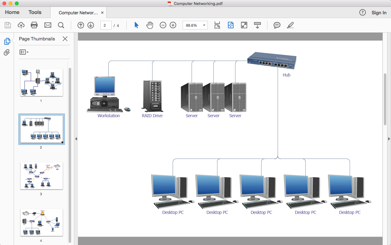
ConceptDraw DIAGRAM offers a range of built-in facilities in order to enable you to quickly edit any diagram or other visualization made using ConceptDraw DIAGRAM, or MS Visio. Grouping shapes, pictures, or objects lets you style, format, rotate, and move them together, as though they were a single object.
HelpDesk

How To Convert a Computer Network Diagram to Adobe PDF

ConceptDraw DIAGRAM allows you to easy transmit your network documentation between different computers with different operating systems and applications using its export capabilities. You can get clear network documentation pack in pdf format and avoid any problems while communicating it with stakeholders.

network layout, network floor plan, network visualization, network topologies, network topology mapper Network Layout Floor Plans

network layout, network floor plan, network visualization, network topologies, network topology mapper
Network Layout Floor Plans solution extends ConceptDraw DIAGRAM software functionality with powerful tools for quick and efficient documentation the network equipment and displaying its location on the professionally designed Network Layout Floor Plans. Never before creation of Network Layout Floor Plans, Network Communication Plans, Network Topologies Plans and Network Topology Maps was not so easy, convenient and fast as with predesigned templates, samples, examples and comprehensive set of vector design elements included to the Network Layout Floor Plans solution. All listed types of plans will be a good support for the future correct cabling and installation of network equipment.
HelpDesk

How to Create an SDL Diagram

Specification and Description Language (SDL) is intended to describe systems that switched state often and rapidly. An SDL diagram is a view of a system, that can depict a single process or complex relationships between a number of elements. The SDL diagram supports a nested hierarchy. A system is divided into blocks, each of them can be described as a process until finally, one can see the initial procedures that make up each process. The advantage of this method is that a system can be viewed in a manageable part that can be followed separately. ConceptDraw Specification and Description Language solution contains the library, with an SDL notation in a vector stencil graphics. The SDL solution also provides a set of samples, to show the level of hierarchical detail that is possible.