This is a schematic process flow diagram of the processes used in a typical oil refinery.
This process flow diagram (PFD) example was redesigned from the Wikimedia Commons file: RefineryFlow.png. [commons.wikimedia.org/ wiki/ File:RefineryFlow.png]
This file is licensed under the Creative Commons Attribution-Share Alike 3.0 Unported license. [creativecommons.org/ licenses/ by-sa/ 3.0/ deed.en]
"An oil refinery or petroleum refinery is an industrial process plant where crude oil is processed and refined into more useful products such as petroleum naphtha, gasoline, diesel fuel, asphalt base, heating oil, kerosene and liquefied petroleum gas. Oil refineries are typically large, sprawling industrial complexes with extensive piping running throughout, carrying streams of fluids between large chemical processing units. In many ways, oil refineries use much of the technology of, and can be thought of, as types of chemical plants. The crude oil feedstock has typically been processed by an oil production plant. There is usually an oil depot (tank farm) at or near an oil refinery for the storage of incoming crude oil feedstock as well as bulk liquid products.
An oil refinery is considered an essential part of the downstream side of the petroleum industry." [Oil refinery. Wikipedia]
The PFD example "Process flow diagram - Typical oil refinery" was created using the ConceptDraw PRO diagramming and vector drawing software extended with the Chemical and Process Engineering solution from the Chemical and Process Engineering area of ConceptDraw Solution Park.
Process Flow Diagram (PFD)
-process-flow-diagram---typical-oil-refinery.png--diagram-flowchart-example.png)
Process Flow Diagram Symbols

Process Flow Diagram

This process flow diagram (PFD) of a typical crude oil distillation unit as used in petroleum crude oil refineries was redrawn from Wikipedia file: Crude Oil Distillation Unit.png. [en.wikipedia.org/ wiki/ File:Crude_ Oil_ Distillation_ Unit.png]
This file is licensed under the Creative Commons Attribution-Share Alike 3.0 Unported license. [creativecommons.org/ licenses/ by-sa/ 3.0/ deed.en]
"An oil refinery or petroleum refinery is an industrial process plant where crude oil is processed and refined into more useful products such as petroleum naphtha, gasoline, diesel fuel, asphalt base, heating oil, kerosene and liquefied petroleum gas. Oil refineries are typically large, sprawling industrial complexes with extensive piping running throughout, carrying streams of fluids between large chemical processing units. In many ways, oil refineries use much of the technology of, and can be thought of, as types of chemical plants. The crude oil feedstock has typically been processed by an oil production plant. There is usually an oil depot (tank farm) at or near an oil refinery for the storage of incoming crude oil feedstock as well as bulk liquid products.
An oil refinery is considered an essential part of the midstream side of the petroleum industry." [en.wikipedia.org/ wiki/ Oil_ refinery]
The process flow diagram (PFD) example "Crude oil distillation" was drawn using the ConceptDraw PRO diagramming and vector drawing software extended with the Chemical and Process Engineering solution from the Chemical and Process Engineering area of ConceptDraw Solution Park.
Process flow diagram (PFD)
-crude-oil-distillation-unit---pfd.png--diagram-flowchart-example.png)
This process flow diagram (PFD) example shows an amine treating system for the removal of gaseous hydrogen sulfide from gas streams. It is used in oil refineries and chemical plants. This PFD sample was redesigned from the Wikimedia Commons file: AmineTreating.png. [commons.wikimedia.org/ wiki/ File:AmineTreating.png]
This file is licensed under the Creative Commons Attribution-Share Alike 3.0 Unported license. [creativecommons.org/ licenses/ by-sa/ 3.0/ deed.en]
"Amine gas treating, also known as gas sweetening and acid gas removal, refers to a group of processes that use aqueous solutions of various alkylamines (commonly referred to simply as amines) to remove hydrogen sulfide (H2S) and carbon dioxide (CO2) from gases. It is a common unit process used in refineries, and is also used in petrochemical plants, natural gas processing plants and other industries.
Processes within oil refineries or chemical processing plants that remove hydrogen sulfide are referred to as "sweetening" processes because the odor of the processed products is improved by the absence of hydrogen sulfide. An alternative to the use of amines involves membrane technology. Membranes are attractive since no reagents are consumed.
Many different amines are used in gas treating:
Diethanolamine (DEA),
Monoethanolamine (MEA),
Methyldiethanolamine (MDEA),
Diisopropanolamine (DIPA),
Aminoethoxyethanol (Diglycolamine) (DGA).
The most commonly used amines in industrial plants are the alkanolamines DEA, MEA, and MDEA. These amines are also used in many oil refineries to remove sour gases from liquid hydrocarbons such as liquified petroleum gas (LPG)." [Amine gas treating. Wikipedia]
The PFD example "Amine treating unit schematic diagram" was drawn using the ConceptDraw PRO diagramming and vector drawing software extended with the Chemical and Process Engineering solution from the Chemical and Process Engineering area of ConceptDraw Solution Park.
Process Flow Diagram (PFD)
-amine-treating-unit-schematic-diagram.png--diagram-flowchart-example.png)
Process Flow Chart

CAD Software for Architectural Designs

Use the libraries with a set of vector objects, templates and samples from the Floor Plans Solution from the Building Plans area of ConceptDraw Solution Park for designing your professional architectural designs.
Example Basic Flowchart. Flowchart Examples

Flow Chart Online

 Chemical and Process Engineering
This chemical engineering solution extends ConceptDraw PRO v.9.5 (or later) with process flow diagram symbols, samples, process diagrams templates and libraries of design elements for creating process and instrumentation diagrams, block flow diagrams (BFD
Accounting Flowchart Symbols

Types of Flowcharts


The vector stencils library "Resources and energy" contains 19 clipart images for drawing illustrations on resources and energy.
"Natural resources occur naturally within environments that exist relatively undisturbed by humanity, in a natural form. A natural resource is often characterized by amounts of biodiversity and geodiversity existent in various ecosystems.
Natural resources are derived from the environment. Some of them are essential for our survival while most are used for satisfying our wants. Natural resources may be further classified in different ways.
Natural resources are materials and components (something that can be used) that can be found within the environment. Every man-made product is composed of natural resources (at its fundamental level). A natural resource may exist as a separate entity such as fresh water, and air, as well as a living organism such as a fish, or it may exist in an alternate form which must be processed to obtain the resource such as metal ores, oil, and most forms of energy." [Natural resource. Wikipedia]
The clip art example "Resources and energy - Vector stencils library" was created in ConceptDraw PRO diagramming and vector drawing software using the Manufacturing and Maintenance solution from the Illustration area of ConceptDraw Solution Park.
Human resources

Batteries

Wind turbine

Transmission tower

Natural gas burner

Solar panel

Lightning

Ionizing radiation hazard sign

High voltage symbol

Atom

Incandescent light bulb

Oil barrels

Power station

Wood

Perpetuum mobile

Hydroelectric dam

Liquefied petroleum gas

Natural gas

Minecart with coal

The stencils library "Asia flags" contains 49 clipart images of Asian state flags.
"... international and national flags used in Asia.
International: Flag of the Council of Europe, Flag of the Commonwealth of Independent States, Flag of the Organization of the Islamic Conference, Flag of the Organization of the Petroleum Exporting Countries, Flag of the Cooperation Council for the Arab States of the Gulf.
Central Asia: Flag of Kazakhstan, Flag of Kyrgyzstan, Flag of Tajikistan, Flag of Turkmenistan, Flag of Uzbekistan.
Eastern Asia: Flag of the People's Republic of China, Flag of Hong Kong (China), Flag of Japan, Flag of North Korea, Flag of South Korea, Flag of Macau (China), Flag of Mongolia, Flag of the Republic of China (Taiwan).
Southeast Asia: Flag of Brunei, Flag of Burma, Flag of Cambodia, Flag of Christmas Island (Australia), Flag of the Cocos (Keeling) Islands (Australia), Flag of East Timor, Flag of Indonesia, Flag of Laos, Flag of Malaysia, Flag of the Philippines, Flag of Singapore, Flag of Thailand, Flag of Vietnam.
Southern Asia: Flag of Bangladesh, Flag of Bhutan, Flag of the British Indian Ocean Territory (United Kingdom), Flag of India, Flag of Maldives, Flag of Nepal, Flag of Pakistan, Flag of Sri Lanka.
Western Asia: Flag of Abkhazia, Flag of Afghanistan, Flag of Akrotiri and Dhekelia (United Kingdom), Flag of Armenia, Flag of Azerbaijan, Flag of Bahrain, Flag of Cyprus, Flag of Egypt, Flag of Georgia, Flag of Iran, Flag of Iraq, Flag of Israel, Flag of Jordan, Flag of Kuwait, Flag of Lebanon, Flag of Nagorno-Karabakh, Flag of Northern Cyprus, Flag of Oman, Flag of Palestine, Flag of Qatar, Flag of Saudi Arabia, Flag of South Ossetia, Flag of Syria, Flag of Turkey, Flag of the United Arab Emirates, Flag of Yemen.
Northern Asia: Flag of Russia." [Flags of Asia. Wikipedia]
The clip art example "Asia flags - Stencils library" was created using the ConceptDraw PRO diagramming and vector drawing software extended with the Continent Maps solution from the Maps area of ConceptDraw Solution Park.
www.conceptdraw.com/ solution-park/ maps-continent
Afghanistan

Armenia

Azerbaijan

Bahrain

Bangladesh

Brunei

Burma

Cambodia

China (PRC)
-asia-flags---stencils-library.png--diagram-flowchart-example.png)
Cyprus

East Timor

Georgia

India

Indonesia

Iran
Iraq

Israel

Japan

Jordan

Kazakhstan

Kuwait

Kyrgyzstan

Laos

Lebanon

Malaysia

Maldives

Mongolia

Nepal

North Korea

Oman

Pakistan

Palestine

Philippines

Qatar

Russia

Saudi Arabia

Singapore

Sri Lanka

South Korea

Syria

Taiwan
Tajikistan

Thailand

Turkey

Turkmenistan

United Arab Emirates

Uzbekistan

Vietnam

Yemen

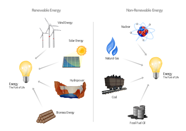
"Consumption of energy resources, (e.g. turning on a light) requires resources and has an effect on the environment. Many electric power plants burn coal, oil or natural gas in order to generate electricity for energy needs. While burning these fossil fuels produces a readily available and instantaneous supply of electricity, it also generates air pollutants including carbon dioxide (CO2), sulfur dioxide and trioxide (SOx) and nitrogen oxides (NOx). Carbon dioxide is an important greenhouse gas which is thought to be responsible for some fraction of the rapid increase in global warming seen especially in the temperature records in the 20th century, as compared with tens of thousands of years worth of temperature records which can be read from ice cores taken in Arctic regions. Burning fossil fuels for electricity generation also releases trace metals such as beryllium, cadmium, chromium, copper, manganese, mercury, nickel, and silver into the environment, which also act as pollutants.
The large-scale use of renewable energy technologies would "greatly mitigate or eliminate a wide range of environmental and human health impacts of energy use". Renewable energy technologies include biofuels, solar heating and cooling, hydroelectric power, solar power, and wind power. Energy conservation and the efficient use of energy would also help." [Energy industry. Environmental impact. Wikipedia]
The Energy resources diagram example was created in the ConceptDraw PRO diagramming and vector drawing software using the Manufacturing and Maintenance solution from the Illustration area of ConceptDraw Solution Park.
Infographics
- Process flow diagram - Typical oil refinery | Process Diagrams | Flow ...
- Process flow diagram - Typical oil refinery | Data Flow Diagram ...
- About Of Refinery Plant And Its Processes Of Drawings
- Process flow diagram - Typical oil refinery | Crude oil distillation unit ...
- Petroleum Industry Plant Layout Process
- Crude oil distillation unit - PFD | Process flow diagram - Typical oil ...
- Diagram Of A Plant
- Oil And Gas Plant Electrical Drawing Diagram
- Process flow diagram - Typical oil refinery | Petroleum products ...
- Electrical Symbol Of Oil Gas Plant Maintenance
- Crude oil distillation unit - PFD | Building Drawing Software for ...
- Drawing Symbols On Petroleum Products
- Process Flowchart | Process Flow Diagram Symbols | Process flow ...
- Petroleum Engineering Tools And Equipments
- Petroleum Products Drawings
- Pipe Line Refinery Drawing
- Drawings Related To Chemical And Petroleum Engineering
- Crude oil distillation unit - PFD | Natural gas condensate - PFD ...
- Diagram Of Petroleum Power Plant