Interior Design Office Layout Plan Design Element


HelpDesk
How to Create a Plant Layout Design

 Office Layout Plans
Office layouts and office plans are a special category of building plans and are often an obligatory requirement for precise and correct construction, design and exploitation office premises and business buildings. Designers and architects strive to make office plans and office floor plans simple and accurate, but at the same time unique, elegant, creative, and even extraordinary to easily increase the effectiveness of the work while attracting a large number of clients.
Interior Design Office Layout Plan Design Element
How To use House Electrical Plan Software


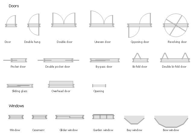
The design elements library Doors contains 69 symbols of doors.
The design elements library Windows contains 34 symbols of windows and casements.
"A door is an opening or closing structure used to block off an entrance, typically consisting of an interior side that faces the inside of a space and an exterior side that faces the outside of that space. While in some cases the interior side of a door may match its exterior side, in other cases there are sharp contrasts between the two sides, such as in the case of the vehicle door. In addition, doors typically consist of a panel that swings on hinges or that slides or spins inside of a space." [Door. Wikipedia]
"A window is an opening in a wall, door or vehicle that allows the passage of light and, if not closed or sealed, air and sound. Modern windows are usually glazed or covered in some other transparent or translucent material. Windows are held in place by frames. Many glazed windows may be opened, to allow ventilation, or closed, to exclude inclement weather." [Window. Wikipedia]
Use the shapes libraries Doors and Windows to create house plans, home plans, floor plan layouts and home designs using the ConceptDraw PRO diagramming and vector drawing software.
The vector stencils libraries Doors and Windows are provided by the Floor Plans solution from the Building Plans area of ConceptDraw Solution Park.
How To use Appliances Symbols for Building Plan

Create Floor Plans Easily with ConceptDraw PRO

How To Create Home Plan with Examples

Building Drawing Software for Design Office Layout Plan

Mini Hotel Floor Plan. Floor Plan Examples

The vector stencils library "Network layout floorplan" contain 34 symbol icons for drawing computer network floor plans, communication equipment layouts, and structured cabling diagrams.
"Structured cabling is building or campus telecommunications cabling infrastructure that consists of a number of standardized smaller elements (hence structured) called subsystems. ...
Structured cabling design and installation is governed by a set of standards that specify wiring data centers, offices, and apartment buildings for data or voice communications using various kinds of cable, most commonly category 5e (CAT-5e), category 6 (CAT-6), and fibre optic cabling and modular connectors. These standards define how to lay the cabling in various topologies in order to meet the needs of the customer, typically using a central patch panel (which is normally 19 inch rack-mounted), from where each modular connection can be used as needed. Each outlet is then patched into a network switch (normally also rack-mounted) for network use or into an IP or PBX (private branch exchange) telephone system patch panel." [Structured cabling. Wikipedia]
The design elements example "Network layout floorplan - Vector stencils library" was created using the ConceptDraw PRO diagramming and vector drawing software extended with the Network Layout Floor Plans solution from the Computer and Networks area of ConceptDraw Solution Park.
PC

Scanner

Switch

Router

Modem

Hub

Rack Mount

Printer

Floor Mounted Outlet

Single Outlet

Duplex Outlet

Direct bus cable

Tops or bottoms bus cable

Side to side bus cable

Multi-tree bus cable

Bottom to side bus cable

Sides bus cable

Door

Door, threshold

Door, stop

Door, stop, threshold

Door, frame

Door, frame, threshold

Door, frame, stop

Door, frame, stop, threshold

Window

Window, sill

Window, sash

Window, sash, sill

Window, frame

Window, frame, sill

Window, frame, sash

Window, frame, sash, sill

Restaurant Floor Plans Software

Room Planning Software

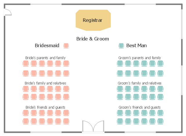
This seating plan sample shows the seat layout at the wedding ceremony.
"A wedding is a ceremony where people are united in marriage. Wedding traditions and customs vary greatly between cultures, ethnic groups, religions, countries, and social classes. Most wedding ceremonies involve an exchange of wedding vows by the couple, presentation of a gift (offering, ring(s), symbolic item, flowers, money), and a public proclamation of marriage by an authority figure or leader. Special wedding garments are often worn, and the ceremony is sometimes followed by a wedding reception. Music, poetry, prayers or readings from religious texts or literature are also commonly incorporated into the ceremony." [Wedding. Wikipedia]
The seat layout example "Wedding ceremony seating plan" was created using the ConceptDraw PRO diagramming and vector drawing software extended with the Seating Plans solution from the Building Plans area of ConceptDraw Solution Park.
Seat layout
- Interior Design Office Layout Plan Design Element | Door Windows ...
- Design elements - Doors and windows | Mini Hotel Floor Plan . Floor ...
- Door And Window Symbol Of Building Layout
- Design elements - Doors and windows | How to Plan and Allocate ...
- House Plan Door Windows Symbols
- Design elements - Doors and windows | Design elements - Windows ...
- Floor Plan Symbol For Slding Glass Doors
- Design elements - Network layout floorplan | Restaurant Floor Plan ...
- Door Plan Symbol
- Doors And Windows Showroom Layout Plan
- Design elements - Doors and windows | Mini Hotel Floor Plan . Floor ...
- Doors Vector Plan
- Plan Of Glass Door In A Residence Plan
- Design elements - Doors and windows
- Window Symbols In Layout Plan
- Network Layout Floor Plans | Design elements - Network layout ...
- Plan Of A Building Symbol For Door And Window
- Design elements - Doors and windows | Mini Hotel Floor Plan . Floor ...
- Design elements - Doors and windows | Network layout floorplan ...
- Design elements - Doors and windows | Design elements - Doors ...