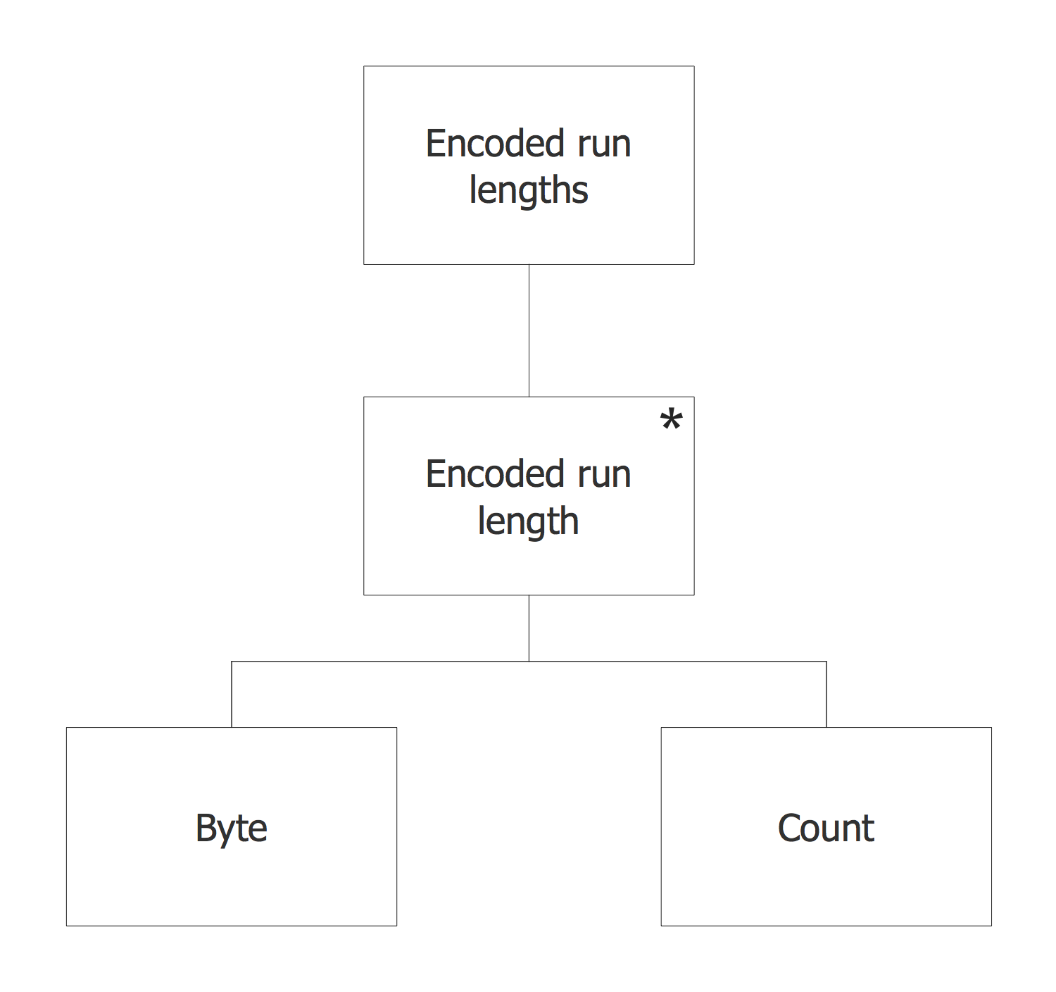
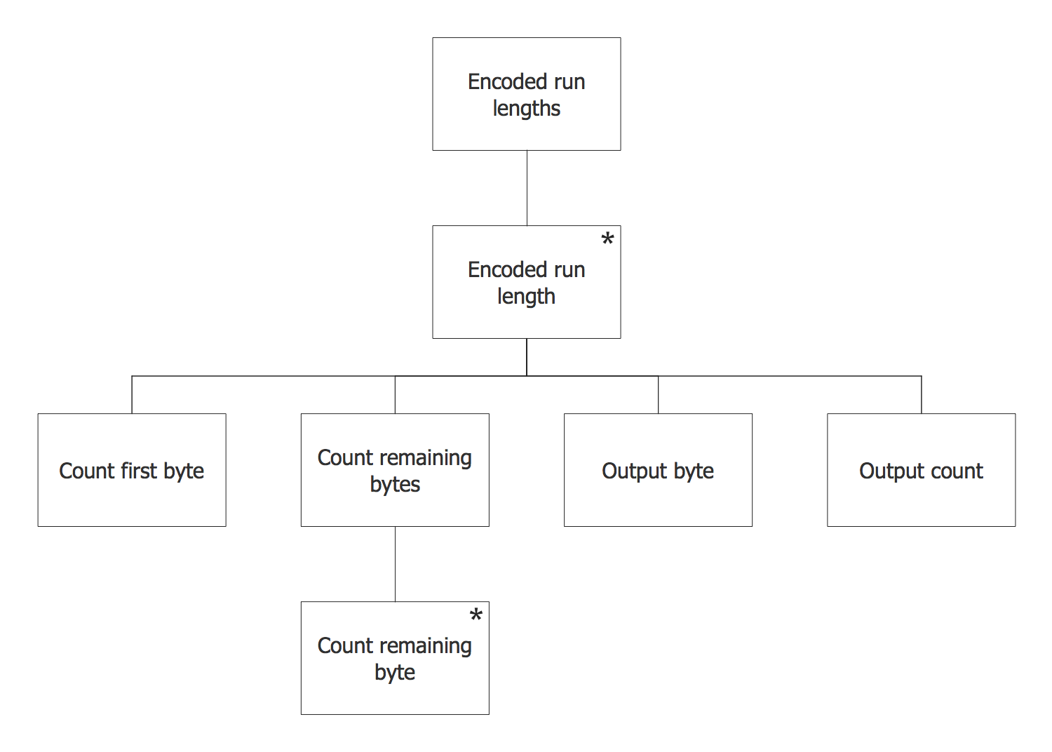
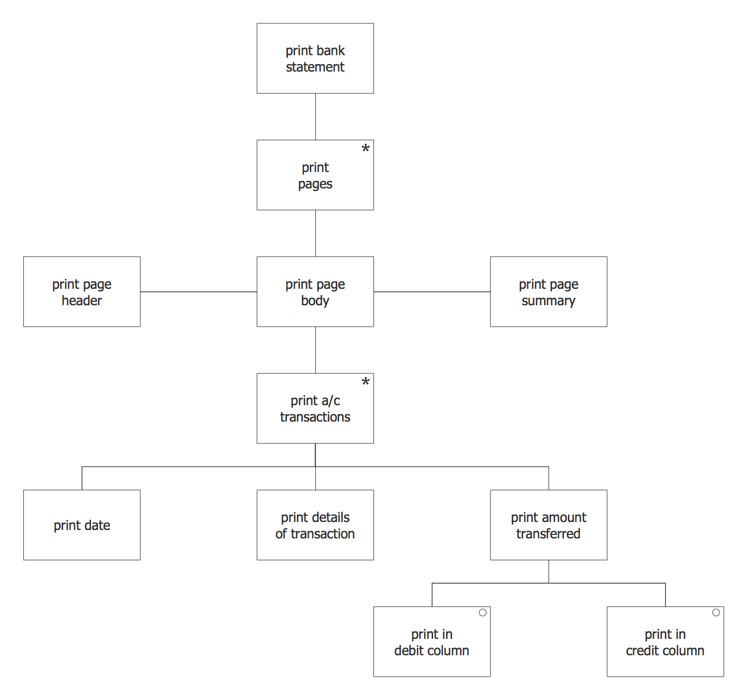
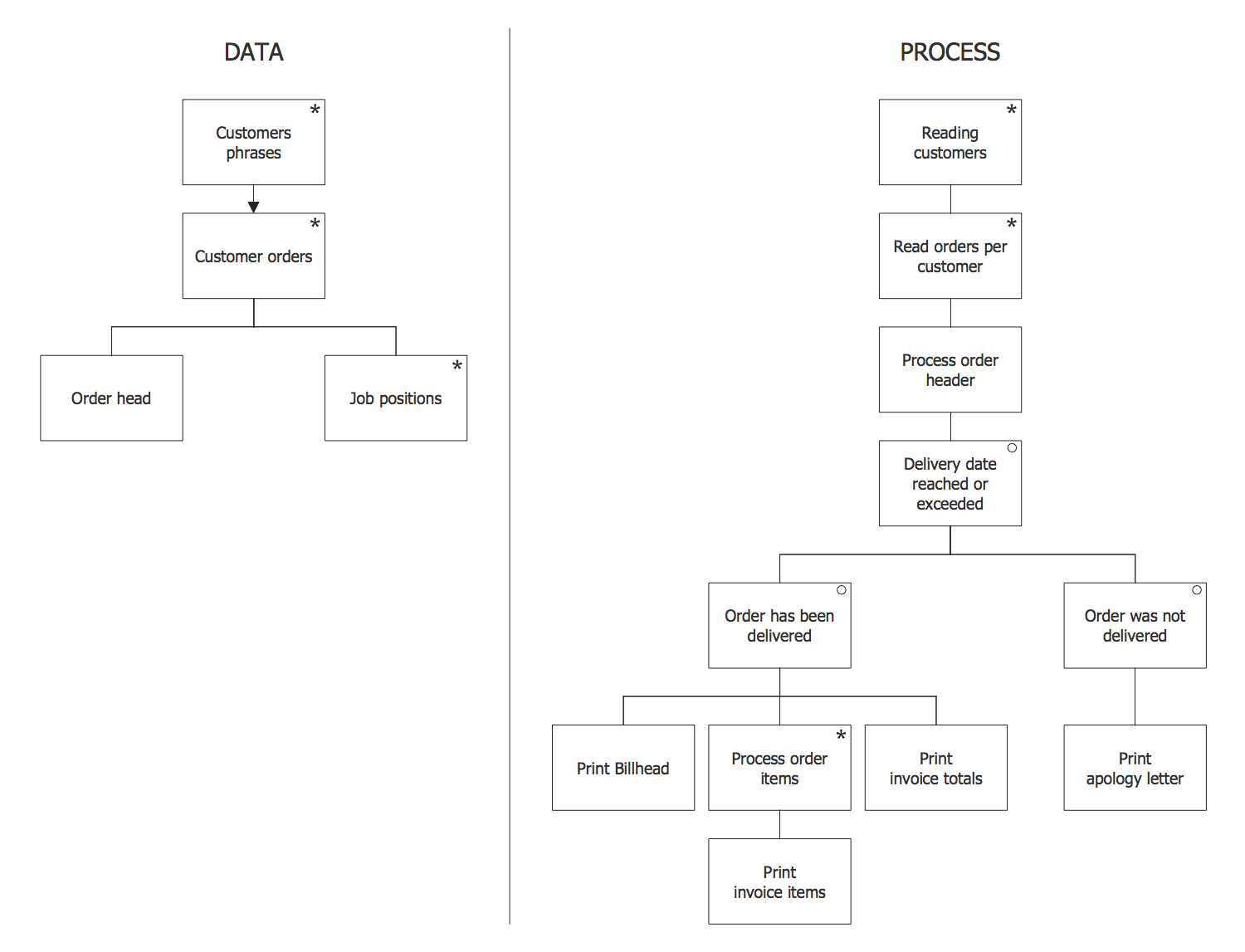
 Jackson Structured Programming (JSP) Diagrams
The Jackson Structured Programming (JSP) Diagram solution extends the functionality and drawing abilities of the ConceptDraw DIAGRAM software with set of illustrative JSP diagrams samples and large variety of predesigned vector objects of actions, processes, procedures, selection, iteration, as well as arrows and connectors to join the objects during Jackson structured development and designing Jackson structured programming diagrams, JSP diagram, Jackson structure diagram (JSD), Program structure diagram. The powerful abilities of this solution make the ConceptDraw DIAGRAM ideal assistant for programmers, software developers, structural programmers, computer engineers, applications constructors, designers, specialists in structured programming and Jackson systems design, and other technical, computer and software specialists.
Jackson Structured Programming
Knowing more about Jackson structured programming, any ConceptDraw DIAGRAM user has a unique opportunity to create the needed Jackson structured programming diagram with the help of this useful tool as well as the Jackson Structured Programming (JSP) Diagrams solution. Having the Jackson Structured Programming (JSP) Diagrams, anyone gets the chance to make the needed diagram as long as it is related to the Jackson structured programming processes. Having such tools as the pre-design elements to be used for simplifying the work of creating the JSP diagrams, any ConceptDraw DIAGRAM user gets a chance to make their own drawing within only a few minutes being based on the already existing symbols.Jackson Systems
Entity structure diagram (ESD) notations may be created in the ConceptDraw DIAGRAM same as any other diagram, including a Jackson Structured Programming (JSP) Diagram. Having the Jackson Structured Programming (JSP) Diagrams solution may simplify the work of drawing the needed illustration representing the given data within only a few minutes. Having the pre-made examples of the JSP diagrams, any ConceptDraw DIAGRAM user is able to make his own unique as well as smart looking drawing in a fun and entertaining way.Structured Programming
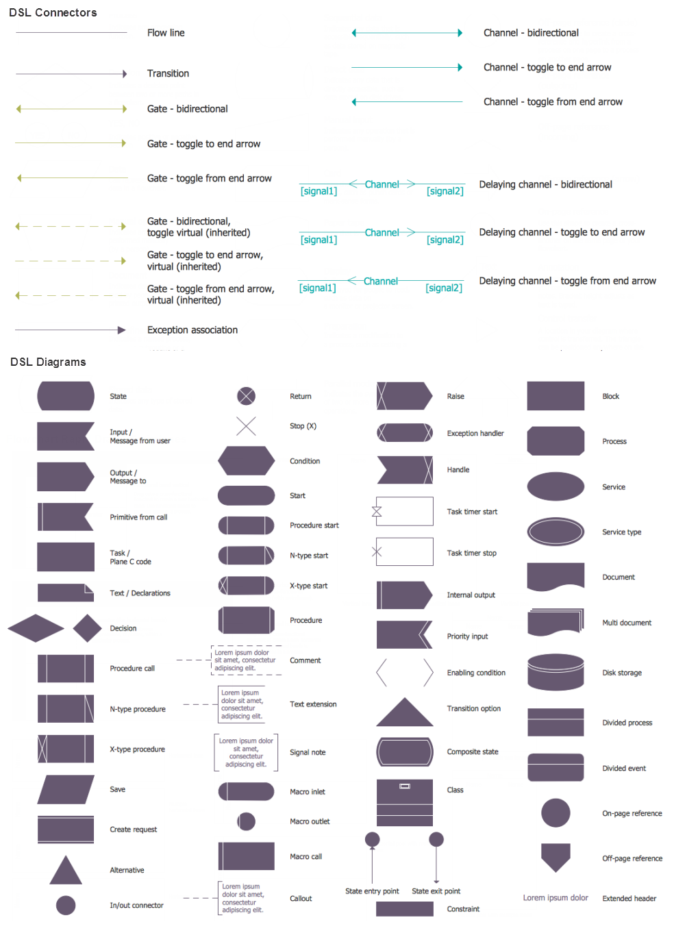
In order to prevent the mistakes in creating the needed design symbols for JSP related drawings, the pre-made stencils are available for all the ConceptDraw DIAGRAM users who install the Jackson Structured Programming (JSP) Diagrams solution. Such representations as the one of an Action/Process, Process, Selection, Tree connector, Iteration, Logical connector and different Procedures, as well as Vertical arrow down, Vertical double arrow, Direct connector and Arrowed direct connector are all available to be used from the stencil library from this solution.Program Structure Diagram
A visual representation of the configuration system, as well as the internal interfaces among such drawing’s CIs, may be always done with the help of the professional tool, such as the ConceptDraw DIAGRAM diagramming software. The structure diagram may be used for identifying the CIs as well as their associated artifacts. Doing it with the aid of ConceptDraw DIAGRAM as well as its extension (the Jackson Structured Programming (JSP) Diagrams solution) may simplify anyone’s work of making such diagrams.Data structure diagram with ConceptDraw DIAGRAM
Data structure diagram (DSD) is intended for description of conceptual models of data (concepts and connections between them) in the graphic format for more obviousness. Data structure diagram includes entities description, connections between them and obligatory conditions and requirements which connect them. Create Data structure diagram with ConceptDraw DIAGRAM.How to Draw ER Diagrams
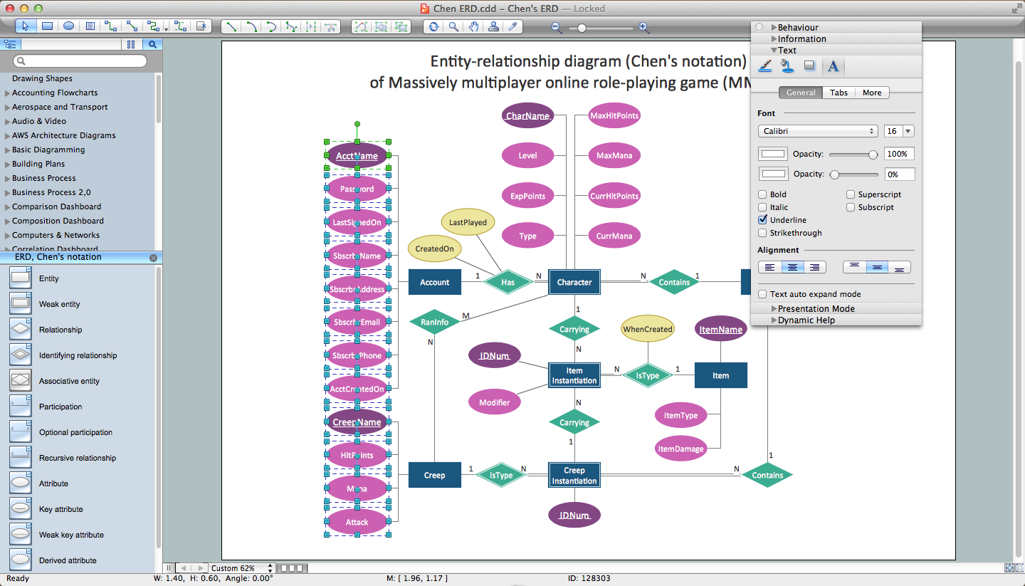
An Entity Relationship (ER) Diagram is a type of flowchart that illustrates the logical structure of databases, how the different entities, such as people, objects or concepts relate to each other within a given system. How to draw ER Diagrams fast and easy? ConceptDraw DIAGRAM diagramming and vector drawing software enhanced with Entity-Relationship Diagram (ERD) solution from Software Development area of ConceptDraw Solution Park offers you the powerful abilities of designing the ER Diagrams and ERD drawings without efforts. This solution includes a lot of predesigned icons advocated by popular Chen's and Crow’s Foot notations, which can be used when describing an enterprise database and depicting it by abstract way. Simply drag the required objects to ConceptDraw document, connect them in a desired way and make style settings. But the easiest and fastest way of drawing ERDs is to make them on the base of ready-to-use Chen ERD and Crow's Foot ERD templates, which are both represented at ConceptDraw STORE.About UML
Use Case Diagram Taxi Service UML. This sample was created in ConceptDraw DIAGRAM diagramming and vector drawing software using the UML Use Case Diagram library of the Rapid UML Solution from the Software Development area of ConceptDraw Solution Park. This sample shows the work of the taxi service and is used by taxi stations, by airports, in the tourism field and delivery service.Software Diagrams
Modern software development begins with designing different software diagrams and also uses a large amount of diagrams in project management and creation graphic documentation. Very popular diagrams that depict a work of applications in various cuts and notations, describe databases and prototype Graphical User Interfaces (GUIs). Software engineering specialists and software designers prefer to use special technical and business graphics tools and applications for easy creation diagrams. One of the most popular is ConceptDraw DIAGRAM diagramming and vector drawing software. ConceptDraw DIAGRAM offers the possibility of drawing with use of wide range of pre-drawn shapes and smart connectors, which allow to focus not on the process of drawing, but on the task's essence. It is a perfect application for design and document development, planning tasks, visualization of data, design the databases, object-oriented design, creation flowcharts of algorithms, modeling business processes, project management, automation of management and development processes, and for many other tasks.System Design
ConceptDraw DIAGRAM diagramming and vector drawing software supplied with Specification and Description Language (SDL) solution from the Engineering area of ConceptDraw Solution Park offers the set of useful tools which make it ideal System Design Software.
 IDEF Business Process Diagrams
Use the IDEF Business Process Diagrams solution to create effective database designs and object-oriented designs, following the integration definition methodology.
 ATM UML Diagrams
The ATM UML Diagrams solution lets you create ATM solutions and UML examples. Use ConceptDraw DIAGRAM as a UML diagram creator to visualize a banking system.
 Object-Role Modeling (ORM) Diagrams
Object-role Modeling (ORM) Diagram solution with powerful vector diagramming and data modeling tools, large quantity of specially developed samples and examples, and rich variety of vector objects corresponding to common ORM notation, ideally suits for developing the comprehensive, clear and visual Object-role Modeling (ORM) diagrams and schematics, understandable for all interested people from the different fields and business directions, for designing the ORM models, and demonstrating advantages from the use of ORM and its notation. It is intended for software developers and computer engineers, specialists in a field of Object-oriented programming (OOP), database architects, web-application constructors and developers, etc.
 Data Flow Diagrams (DFD)
Data Flow Diagrams solution extends ConceptDraw DIAGRAM software with templates, samples and libraries of vector stencils for drawing the data flow diagrams (DFD).
 SYSML
SYSML
The SysML solution helps to present diagrams using Systems Modeling Language; a perfect tool for system engineering.
 Business Process Diagrams
Business Process Flow Diagrams solution extends the ConceptDraw DIAGRAM BPM software with RapidDraw interface, templates, business process diagrams examples and numerous libraries based on the BPMN 1.2 and BPMN 2.0 standards, which give you the possibility to visualize equally easy simple and complex processes, to design business models, to quickly develop and document in details any business processes on the stages of project’s planning and implementation.
 Rapid UML
Rapid UML solution extends ConceptDraw DIAGRAM software with templates, samples and libraries of vector stencils for quick drawing the UML diagrams using Rapid Draw technology.
Jacobson Use Cases Diagram
The vector stencils library UML Use Case contains specific symbols of the UML notation such as actors, actions, associations and relationships for the ConceptDraw DIAGRAM diagramming and vector drawing software. This library is contained in the Rapid UML solution from Software Development area of ConceptDraw Solution Park.
 Entity-Relationship Diagram (ERD)
An Entity-Relationship Diagram (ERD) is a visual presentation of entities and relationships. That type of diagrams is often used in the semi-structured or unstructured data in databases and information systems. At first glance ERD is similar to a flowch
 Flowcharts
The Flowcharts solution for ConceptDraw DIAGRAM is a comprehensive set of examples and samples in several varied color themes for professionals that need to represent graphically a process. Solution value is added by the basic flow chart template and shapes' libraries of flowchart notation. ConceptDraw DIAGRAM flow chart creator lets one depict the processes of any complexity and length, as well as design the Flowchart either vertically or horizontally.
- Jackson Structured Programming (JSP) Diagrams | Example of DFD ...
- JSD - Jackson system development | Data Flow Diagram | Jackson ...
- ATM UML Diagrams | Diagramming Software for Design UML ...
- Structured Systems Analysis and Design Method. SSADM with ...
- Entity-Relationship Diagram (ERD) | ERD Symbols and Meanings ...
- Diagrams | Control Structure Diagram In Visual Basic
- Jackson Structured Programming (JSP) Diagrams | Data Flow ...
- Electrical Symbols — Analog and Digital Logic | UML Use Case ...
- Basic Flowchart Symbols and Meaning | Jackson Structured ...
- Data structure diagram with ConceptDraw DIAGRAM | Program ...
- Flowchart Components | Entity Relationship Diagram Examples ...
- Example of DFD for Online Store (Data Flow Diagram) DFD ...
- How to Create a SIPOC Diagram | Business Process Mapping ...
- UML Component Diagram Example - Online Shopping | State ...
- UML Component Diagram Example - Online Shopping | Example of ...
- | Electrical Symbols — Power Sources | Entity Relationship Diagram ...
- UML Component Diagram Example - Online Shopping | How to ...
- Data Flow Diagram
- Bank Management System Project Pdf With Ppt
- UML Component Diagram Example - Online Shopping | UML ...
