Cloud Computing

This example was created in ConceptDraw PRO using the Computer and Networks Area of ConceptDraw Solution Park and shows the Cloud Computing.
ER Diagram for Cloud Computing

Amazon Cloud

How to Build Cloud Computing Diagram Principal Cloud Manufacturing

For documenting the Cloud Computing Architecture with a goal to facilitate the communication between stakeholders are successfully used the Cloud Computing Architecture diagrams. It is convenient and easy to draw various Cloud Computing Architecture diagrams in ConceptDraw PRO software with help of tools of the Cloud Computing Diagrams Solution from the Computer and Networks Area of ConceptDraw Solution Park.
Introduction to Cloud Computing Architecture

Cloud Computing Architecture

Cloud Computing Architecture Diagrams

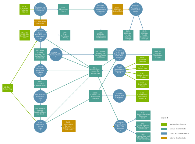
This DFD sample was created on the base of the figure from the NASA website. [asd-www.larc.nasa.gov/ ATBD/ DFD.html]
"Clouds and the Earth's Radiant Energy System (CERES).
EOS-Terra: Understanding Earth's Clouds and Climate.
The Clouds and the Earth's Radiant Energy System (CERES) instrument is one of several that will be flown aboard the Earth Observing System's Terra spacecraft, scheduled for launch in late1999. The data from the CERES instrument will be used to study the energy exchanged between the Sun; the Earth's atmosphere, surface and clouds; and outer space.
The CERES EOS-Terra instrument will be the second CERES instrument in Earth orbit. The first CERES instrument is currently orbiting the Earth aboard the Tropical Rainfall Measuring Mission observatory, which was launched in November 1997. Early results of the TRMM mission show that the first CERES has provided better measurement capabilities than any previous satellite instrument of its kind.
What CERES Will Measure.
CERES will measure the energy at the top of the atmosphere, as well as estimate energy levels in the atmosphere and at the Earth's surface. Using information from very high resolution cloud imaging instruments on the same spacecraft, CERES also will determine cloud properties, including cloud amount, altitude, thickness, and the size of the cloud particles. All of these measurements are critical for advancing our understanding of the Earth's total climate system and further improving climate prediction models.
The CERES instrument is based on NASA Langley's highly successful Earth Radiation Budget Experiment (ERBE) which used three satellites to provide global energy budget measurements from 1984 to 1990." [nasa.gov/ centers/ langley/ news/ factsheets/ CERES.html]
The DFD example "CERES data flow diagram" was created using the ConceptDraw PRO diagramming and vector drawing software extended with the Data Flow Diagrams solution from the Software Development area of ConceptDraw Solution Park.
DFD
HelpDesk
How to Create an Azure Architecture Diagram Using ConceptDraw PRO

What is Cloud Computing

The vector stencils library "AWS simple icons" contains 97 symbol icons of Amazon Web Services (AWS) elements for drawing AWS cloud architecture diagrams.
"Amazon Web Services (abbreviated AWS) is a collection of remote computing services (also called web services) that together make up a cloud computing platform, offered over the Internet by Amazon.com. The most central and well-known of these services are Amazon EC2 and Amazon S3. The service is advertised as providing a large computing capacity (potentially many servers) much faster and cheaper than building a physical server farm." [Amazon Web Services. Wikipedia]
The symbols example "AWS simple icons - Vector stencils library" was created using the ConceptDraw PRO diagramming and vector drawing software extended with the AWS Architecture Diagrams solution from the Computer and Networks area of ConceptDraw Solution Park.
www.conceptdraw.com/ solution-park/ computer-networks-aws
Amazon Elastic Compute Cloud (EC2)
Instance
Instances
AMI
DB on Instance
Instance with CloudWatch
Elastic IP
Amazon Elastic MapReduce
Cluster
HDFS Cluster
Auto Scaling
Amazon Simple Storage Service (S3)
Bucket
Bucket with Objects
Object
AWS Import/Export
AWS Storage Gateway Service
Amazon Elastic Block Storage (EBS)
Volume
Snapshot
Amazon CloudFront
Download Distribution
Streaming Distribution
Edge Location
Amazon CloudWatch
Alarm
Elastic Load Balancer
AWS Direct Connect
Amazon Route 53
Hosted Zone
Route Table
Amazon Virtual Private Cloud (VPC)
VPN Connection
VPN Gateway
Customer Gateway
Internet Gateway
Router
Amazon SimpleDB
Domain
Item
Items
Attribute
Attributes
Amazon Relational Database Service (RDS)
RDS DB Instance
RDS DB Instance Standby (Multi-AZ)
RDS DB Instance Read Replica
Oracle DB Instance
MySQL DB Instance
Table
Amazon DynamoDB
Amazon ElastiCache
ElastiCache Cache Node
Amazon Simple Email Service (SES)
Email
Amazon Simple Notification Service (SNS)
Topic
Email Notification
HTTP Notification
Amazon Simple Queue Service (SQS)
Queue
Message
Amazon Simple Workflow Service (SWF)
Decider
Worker
AWS CloudFormation
Template
Stack
AWS Elastic Beanstalk
Application
Amazon Mechanical Turk
Human Intelligence Tasks (HIT)
Assignment/Task
Workers
Requester
Users
User
Client
Mobile Client
Multimedia
Corporate Data Center
Traditional Server
Internet
AWS Management Console
IAM Add-on
Example: IAM Add-on
Availability Zone
Region
Security Group
Elastic Beanstalk Container
EC2 Instance Contents
VPC Subnet
Server Contents
Virtual Private Cloud
AWS Cloud
Corporate Data Center
Auto Scaling Group
Diagram Flow Chart

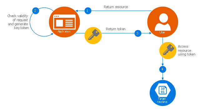
This Azure cloud architecture pattern diagram template was created on the base of figure in the article "Valet Key Pattern" from the Microsoft Developer Network (MSDN) website.
"Valet Key Pattern.
Use a token or key that provides clients with restricted direct access to a specific resource or service in order to offload data transfer operations from the application code. This pattern is particularly useful in applications that use cloud-hosted storage systems or queues, and can minimize cost and maximize scalability and performance. ...
Client programs and web browsers often need to read and write files or data streams to and from an application’s storage. ...
Data stores have the capability to handle upload and download of data directly, without requiring the application to perform any processing to move this data, but this typically requires the client to have access to the security credentials for the store.
... applications must be able to securely control access to data in a granular way, but still reduce the load on the server by setting up this connection and then allowing the client to communicate directly with the data store to perform the required read or write operations. ...
To resolve the problem of controlling access to a data store where the store itself cannot manage authentication and authorization of clients, one typical solution is to restrict access to the data store’s public connection and provide the client with a key or token that the data store itself can validate.
This key or token is usually referred to as a valet key. It provides time-limited access to specific resources and allows only predefined operations such as reading and writing to storage or queues, or uploading and downloading in a web browser. Applications can create and issue valet keys to client devices and web browsers quickly and easily, allowing clients to perform the required operations without requiring the application to directly handle the data transfer. This removes the processing overhead, and the consequent impact on performance and scalability, from the application and the server." [msdn.microsoft.com/ ru-RU/ library/ dn568102.aspx]
The Azure cloud system architecture diagram template "Valet key pattern" for the ConceptDraw PRO diagramming and vector drawing software is included in the Azure Architecture solutin from the Computer and Networks area of ConceptDraw Solution Park.
Cloud computing system architecture diagram template
HelpDesk
How to Create a Data Flow Diagram using ConceptDraw PRO
 example")
- Data Cloud Computing
- Cloud Computing Diagrams | Cloud Computing Architecture ...
- CERES data flow diagram | Cloud Computing Architecture Diagrams ...
- ConceptDraw PRO ER Diagram Tool | Data Flow Diagrams | ER ...
- Cloud Transport Management System Er Diagram
- What Is Cloud Data
- Active Directory Diagrams | Data Flow Diagrams (DFD) | Cloud ...
- Cloud Computing Diagrams | Cloud Computing Architecture ...
- Diagramming tool - Amazon Web Services and Cloud Computing ...
- ER Diagram for Cloud Computing | Cloud Computing Architecture ...
- ATM UML Diagrams | Cloud Computing Diagrams | AWS ...
- Diagramming tool - Amazon Web Services and Cloud Computing ...
- Cloud Computing | Cloud Computing Architecture | Valet key pattern ...
- Cloud Computing Architecture Diagrams
- Cloud Computing Diagrams | Cloud Computing Architecture ...
- Using The Cloud For Business
- Cloud Computing Architecture Diagrams | Amazon Web Services ...
- Data Sharing From Pc To Pc Diagram
- Introduction to Cloud Computing Architecture | Cloud Computing ...
- Cloud Computing Architecture | How to Install ConceptDraw on a ...