The vector stencils library "Windows 8 apps" contains 40 shortcut icons of Windows 8 software applications.
Use this shortcut UI icon set to design graphic user interface (GUI) prototypes of your software apps for Windows 8.
"In computing, a file shortcut is a handle in a user interface that allows the user to find a file or resource located in a different directory or folder from the place where the shortcut is located.
Shortcuts are typically implemented as a small file containing a target URI or GUID to an object, or the name of a target program file that the shortcut represents. The shortcut might additionally specify parameters to be passed to the target program when it is run. Each shortcut can have its own icon. Shortcuts are very commonly placed on a desktop, in an application launcher panel such as the Microsoft Windows Start menu, or in the main menu of a desktop environment. ...
File shortcuts (also known as shell links) were introduced in Windows 95. Microsoft Windows uses .lnk as the filename extension for shortcuts to local files, and .URL for shortcuts to remote files, like web pages. Commonly referred to as "shortcuts" or "link files", both are displayed with a curled arrow overlay icon by default, and no filename extension. ...
Shortcut files can be used to launch programs in minimized or maximized window states if the program supports it. ...
Beginning with Windows 7, some shortcuts also store Application User Model IDs (AppUserModelIDs). Instead of the target command line, AppUserModelIDs may directly be used to launch applications. Shortcuts with AppUserModelIDs are used by some desktop programs and all WinRT Modern apps for launching." [File shortcut. Wikipedia]
The shortcut icons example "Windows 8 apps - Vector stencils library" was created using the ConceptDraw PRO diagramming and vector drawing software extended with the Windows 8 User Interface solution from the Software Development area of ConceptDraw Solution Park.
Alarms
Calculator
Calendar
Camera
Dashboard

Database

Exel 2013
Finance

Food + Drink

Games

Health + Fitness

Help+Tips

Internet Explorer

Language
Mail
Maps
Music

News

SkyDrive
OneNote
Outlook 2013
PC Settings
People

Photos

PowerPoint 2013
Reading List

Scanner
Sound Recorder

Skype
Sports

Store
Spreadsheet
Telemetry Center

Travel

Upload Center

Video

Viewer
Visio 2013
Weather

Word 2013
Visio Files and ConceptDraw

Swim Lane Flowchart Symbols

Martin ERD Diagram

Gane Sarson Diagram

Example of DFD for Online Store (Data Flow Diagram)


Chen ERD Diagram

How to create a UML Diagram

HelpDesk
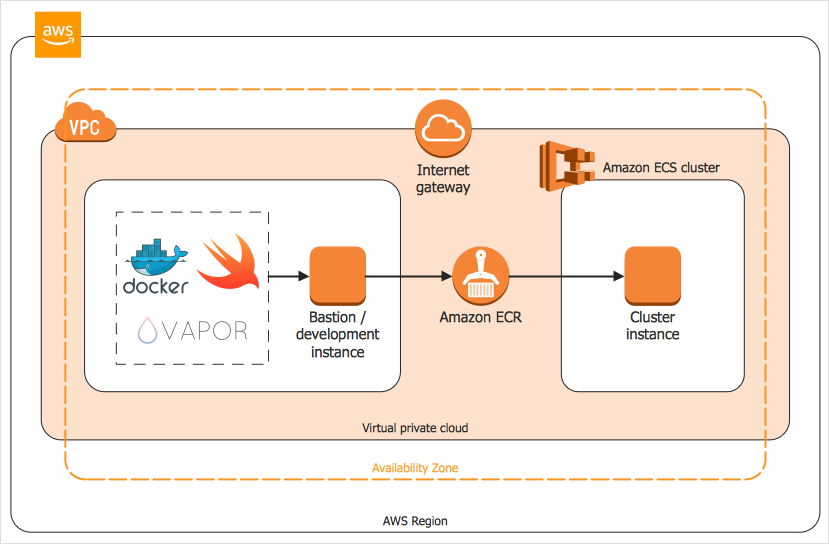
How to Create an AWS Architecture Diagram
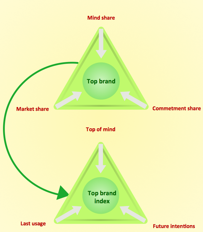
How to Create a Pyramid Diagram
Developing Entity Relationship Diagrams

 Chen Notation
The Chen Notation solution extends ConceptDraw DIAGRAM software with rich collection of ERD samples and selection of special Chen's notation icons for effective database design, data modeling, and visual representation of relationships between the entities on the ER diagrams designed with Chen notation.
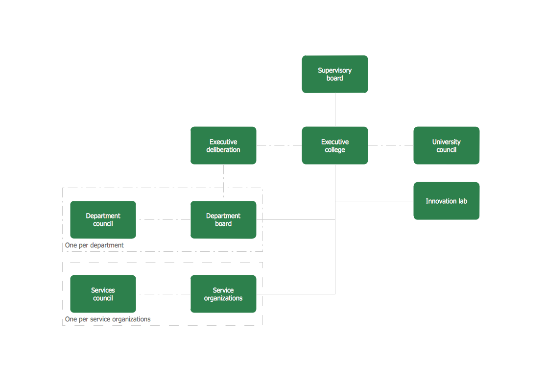
Organogram Software
Data Modeling Diagram

 Entity-Relationship Diagram (ERD)
An Entity-Relationship Diagram (ERD) is a visual presentation of entities and relationships. That type of diagrams is often used in the semi-structured or unstructured data in databases and information systems. At first glance ERD is similar to a flowch
- Icon App Windows 8
- Glyph icons - Vector stencils library | Database Flowchart Symbols ...
- Database Icon Png
- Design elements - Windows 8 round icons | Window elements ...
- Windows 8 Game Icon
- Windows 8 apps - Vector stencils library | Design elements - Icons ...
- Windows Applications Icon
- Cisco Switches and Hubs. Cisco icons , shapes, stencils and symbols
- Design elements - IVR computer | Glyph icons - Vector stencils ...
- App icons - Vector stencils library | Windows 8 apps - Vector stencils ...
- Design elements - Apps icons | App icons - Vector stencils library ...
- Windows 8 Video Icon
- Gui Icons Windows
- Glyph icons - Vector stencils library | Windows 8 apps - Vector ...
- Glyph icons - Vector stencils library | App icons - Vector stencils ...
- Entity Relationship Diagram Symbols | ERD Symbols and Meanings ...
- Flowchart design. Flowchart symbols, shapes, stencils and icons ...
- App icons - Vector stencils library | Best Vector Drawing Application ...
- Urgent Icon
- Windows 8 apps - Vector stencils library | Cisco Routers. Cisco icons ...