UML Collaboration Diagram (UML2.0)


UML Diagram

UML Collaboration Diagram Example Illustration

UML Diagram Types List

UML Collaboration Diagram. Design Elements

UML Use Case Diagram Example - Estate Agency

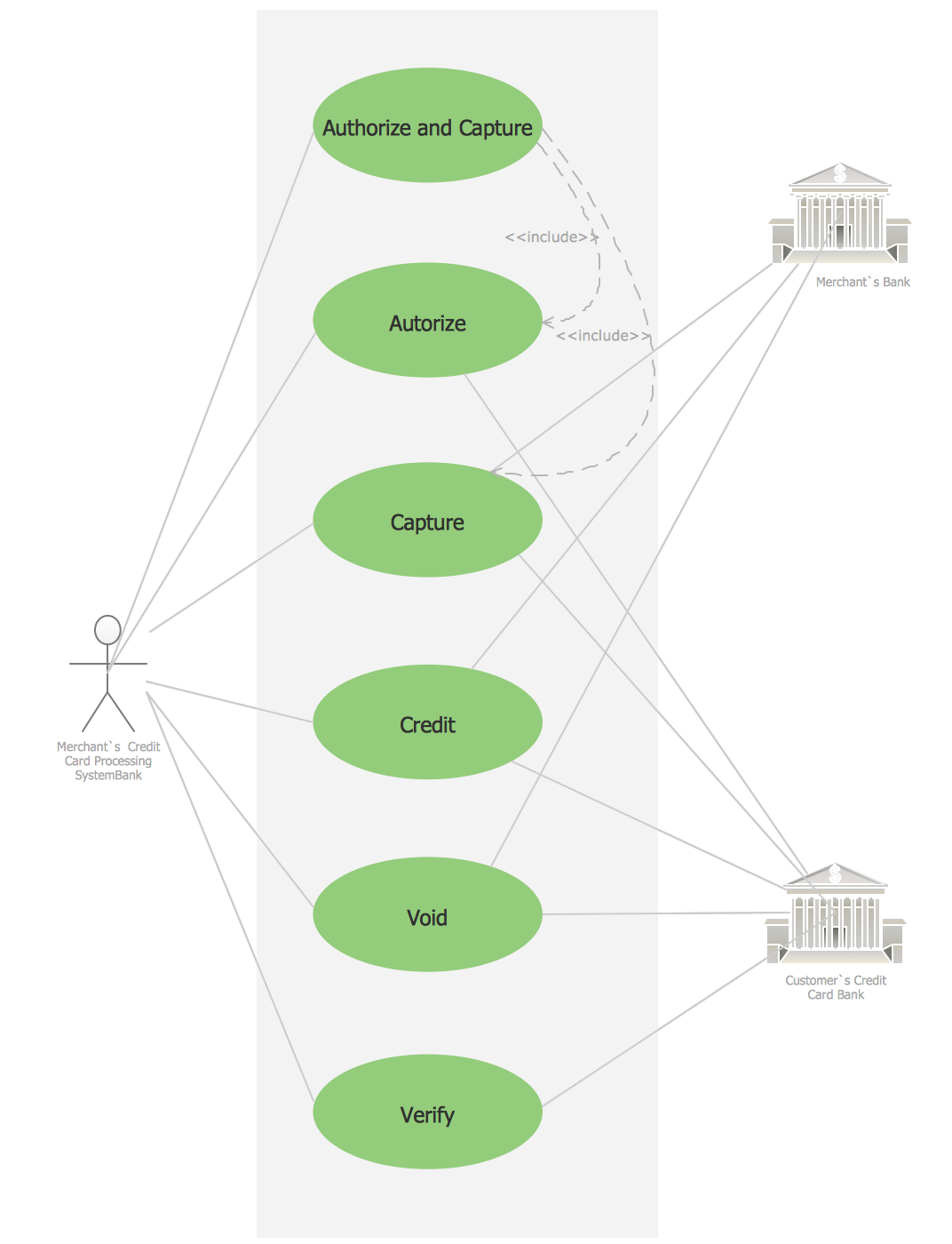
Credit Card Processing System UML Diagram
An Event-driven Process Chain (EPC) - flowchart used for business process modelling

Diagramming Software for Design UML Communication Diagrams

UML Component Diagram Example - Online Shopping

UML Class Diagram Generalization Example UML Diagrams

UML Notation

Structured Systems Analysis and Design Method (SSADM) with ConceptDraw DIAGRAM

 Rapid UML
Rapid UML solution extends ConceptDraw DIAGRAM software with templates, samples and libraries of vector stencils for quick drawing the UML diagrams using Rapid Draw technology.
- Draw A Sequence And Collaboration Diagrams For Order Processing
- Collaboration Diagram Of Order Management System
- Object Diagram For Order Management System
- Collaboration Diagram For Online Food Ordering System
- Uml Diagrams Order
- Order Management System Uml Case Diagram Examples
- Order Management System State Diagram
- Collaboration Diagram For A Transport Management System
- Activity Diagram For Order Management System
- Collaboration Diagram Of Transport Management System
- Class Diagram For Order Management
- Deployement Diagram For Order Management System
- Deployment Diagram For Online Ordering System
- Diagramming Software for Design UML Collaboration Diagrams ...
- Credit Card Processing System UML Diagram | Communication ...
- UML Class Diagram Generalization Example UML Diagrams ...
- Find Collaboration Diagram For Transport Management System
- Draw A Use Case Diagram For Order Processing System In
- Communication Diagram UML2.0 / Collaboration UML1.x | Credit ...
- Order Management System Diagrams