Basic Flowchart Symbols and Meaning


Process Flow Diagram Symbols

Electrical Symbols, Electrical Diagram Symbols

 ATM UML Diagrams
The ATM UML Diagrams solution lets you create ATM solutions and UML examples. Use ConceptDraw DIAGRAM as a UML diagram creator to visualize a banking system.
 Plant Layout Plans
Plant Layout Plans solution can be used for power plant design and plant layout design, for making the needed building plant plans and plant layouts looking professionally good. Having the newest plant layout software, the plant design solutions and in particular the ConceptDraw’s Plant Layout Plans solution, including the pre-made templates, examples of the plant layout plans, and the stencil libraries with the design elements, the architects, electricians, interior designers, builders, telecommunications managers, plant design engineers, and other technicians can use them to create the professionally looking drawings within only a few minutes.
Types of Flowchart - Overview


Value stream with ConceptDraw DIAGRAM

Electrical Drawing Software and Electrical Symbols

UML Deployment Diagram. Design Elements

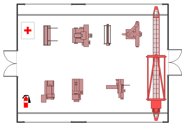
The example "Factory layout floor plan" shows manufacturing machines and equipment in the plant warehouse.
"A factory (previously manufactory) or manufacturing plant is an industrial site, usually consisting of buildings and machinery, or more commonly a complex having several buildings, where workers manufacture goods or operate machines processing one product into another.
Most modern factories have large warehouses or warehouse-like facilities that contain heavy equipment used for assembly line production. Large factories tend to be located with access to multiple modes of transportation, with some having rail, highway and water loading and unloading facilities." [Factory. Wikipedia]
The example "Factory layout floor plan" was created using the ConceptDraw PRO diagramming and vector drawing software extended with the Plant Layout Plans solution from the Building Plans area of ConceptDraw Solution Park.
Industrial equipment layout
 HVAC Plans
Use HVAC Plans solution to create professional, clear and vivid HVAC-systems design plans, which represent effectively your HVAC marketing plan ideas, develop plans for modern ventilation units, central air heaters, to display the refrigeration systems for automated buildings control, environmental control, and energy systems.
Cisco Icons

The vector stencils library "Vessels" contains 40 symbols of vessels, containers, tanks, drums, and basins.
Use these shapes for drawing process flow diagrams (PFD), materials handling systems, and feed systems in industrial and manufacturing processes.
"A pressure vessel is a closed container designed to hold gases or liquids at a pressure substantially different from the ambient pressure.
The pressure differential is dangerous and fatal accidents have occurred in the history of pressure vessel development and operation. Consequently, pressure vessel design, manufacture, and operation are regulated by engineering authorities backed by legislation. For these reasons, the definition of a pressure vessel varies from country to country, but involves parameters such as maximum safe operating pressure and temperature." [Pressure vessel. Wikipedia]
The example "Design elements - Vessels" was created using the ConceptDraw PRO diagramming and vector drawing software extended with the Chemical and Process Engineering solution from the Engineering area of ConceptDraw Solution Park.
Vessel symbols

Retract resistor check valve application: pneumatic cylinder, piston driven by Compressed air through 2 Retract resistor check valves.
"A check valve, clack valve, non-return valve or one-way valve is a valve that normally allows fluid (liquid or gas) to flow through it in only one direction.
Check valves are two-port valves, meaning they have two openings in the body, one for fluid to enter and the other for fluid to leave. There are various types of check valves used in a wide variety of applications. Check valves are often part of common household items. Although they are available in a wide range of sizes and costs, check valves generally are very small, simple, or inexpensive. Check valves work automatically and most are not controlled by a person or any external control; accordingly, most do not have any valve handle or stem. The bodies (external shells) of most check valves are made of plastic or metal.
An important concept in check valves is the cracking pressure which is the minimum upstream pressure at which the valve will operate. Typically the check valve is designed for and can therefore be specified for a specific cracking pressure.
Heart valves are essentially inlet and outlet check valves for the heart ventricles, since the ventricles act as pumps." [Check valve. Wikipedia]
This hydraulic schematic example was redrawn using ConceptDraw PRO diagramming and vector drawing software from the Wikimedia Commons file: Retract resistor check valve application.png.
[commons.wikimedia.org/ wiki/ File:Retract_ resistor_ check_ valve_ application.png]
The hydraulic engineering drawing example "Retract resistor check valve application" was created using the ConceptDraw PRO diagramming and vector drawing software extended with the Mechanical Engineering solution from the Engineering area of ConceptDraw Solution Park.
Hydraulic schematic

The vector stencils library "Valves and fittings" contains 104 symbols of valve components.
Use these icons for drawing industrial piping systems; process, vacuum, and fluids piping; hydraulics piping; air and gas piping; materials distribution; and liquid transfer systems.
"A valve is a device that regulates, directs or controls the flow of a fluid (gases, liquids, fluidized solids, or slurries) by opening, closing, or partially obstructing various passageways. Valves are technically valves fittings, but are usually discussed as a separate category. In an open valve, fluid flows in a direction from higher pressure to lower pressure.
The simplest, and very ancient, valve is simply a freely hinged flap which drops to obstruct fluid (gas or liquid) flow in one direction, but is pushed open by flow in the opposite direction. This is called a check valve, as it prevents or "checks" the flow in one direction. ...
Valves are found in virtually every industrial process, including water & sewage processing, mining, power generation, processing of oil, gas & petroleum, food manufacturing, chemical & plastic manufacturing and many other fields. ...
Valves may be operated manually, either by a handle, lever, pedal or wheel. Valves may also be automatic, driven by changes in pressure, temperature, or flow. These changes may act upon a diaphragm or a piston which in turn activates the valve, examples of this type of valve found commonly are safety valves fitted to hot water systems or boilers.
More complex control systems using valves requiring automatic control based on an external input (i.e., regulating flow through a pipe to a changing set point) require an actuator. An actuator will stroke the valve depending on its input and set-up, allowing the valve to be positioned accurately, and allowing control over a variety of requirements." [Valve. Wikipedia]
The example "Design elements - Valves and fittings" was created using the ConceptDraw PRO diagramming and vector drawing software extended with the Chemical and Process Engineering solution from the Engineering area of ConceptDraw Solution Park.
Valves and fittings symbols

The vector stencils library "Fluid power equipment" contains 113 symbols of hydraulic and pneumatic equipment including pumps, motors, air compressors, cylinders, meters, gauges, and actuators.
Use it to design fluid power and hydraulic control systems in the ConceptDraw PRO diagramming and vector drawing software extended with the Mechanical Engineering solution from the Engineering area of ConceptDraw Solution Park.
www.conceptdraw.com/ solution-park/ engineering-mechanical
Use it to design fluid power and hydraulic control systems in the ConceptDraw PRO diagramming and vector drawing software extended with the Mechanical Engineering solution from the Engineering area of ConceptDraw Solution Park.
www.conceptdraw.com/ solution-park/ engineering-mechanical
Actuator (semi-rotary), pneumatic
,-pneumatic-fluid-power-equipment---vector-stencils-library.png--diagram-flowchart-example.png)
Actuator (semi-rotary), hydraulic
,-hydraulic-fluid-power-equipment---vector-stencils-library.png--diagram-flowchart-example.png)
Drive unit, pneumatic

Drive unit, hydraulic

Sgl-act. cylinder, pneum., left spring

Sgl-act. cylinder, pneum., right spring

Sgl-act. cylinder, pneumatic

Sgl-act. cylinder, hydr., left spring

Sgl-act. cylinder, hydr., right spring

Sgl-act. cylinder, hydraulic

Dbl-act. cylinder, pneumatic

Dbl-act. cylinder, pneum., sgl cushion

Dbl-act. cylinder, pneum., dbl cushion

Dbl-act. cylinder, pneum., adjustable

Dbl-act. cylinder, pneum., sgl cushion, adj.

Dbl-act. cylinder, pneum., dbl cushion, adj.

Dbl-act. cylinder, hydraulic

Dbl-act. cylinder, hydr., sgl cushion

Dbl-act. cylinder, hydr., dbl cushion

Dbl-act. cylinder, hydr., adjustable

Dbl-act. cylinder, hydr., sgl cushion, adj.

Dbl-act. cylinder, hydr., dbl cushion, adj.

Dbl-act. cylinder, magnetic

Dbl-act. cylinder, magn., sgl cushion

Dbl-act. cylinder, magn., dbl cushion

Dbl-act. cylinder, magn., adjustable

Dbl-act. cylinder, magn., sgl cushion, adj.

Dbl-act. cylinder, magn., dbl cushion, adj.

Dbl-act. dbl-end. cylinder, pneumatic

Dbl-act. dbl-end. cylinder, pneum., sgl cushion

Dbl-act. dbl-end. cylinder, pneum., dbl cushion

Dbl-act. dbl-end. cylinder, pneum., adjustable

Dbl-act. dbl-end. cylinder, pneum., sgl cushion, adj.

Dbl-act. dbl-end. cylinder, pneum., dbl cushion, adj.

Dbl-act. dbl-end. cylinder, hydraulic

Dbl-act. dbl-end. cylinder, hydr., sgl cushion

Dbl-act. dbl-end. cylinder, hydr., dbl cushion

Dbl-act. dbl-end. cylinder, hydr., adjustable

Dbl-act. dbl-end. cylinder, hydr., sgl cushion, adj.

Dbl-act. dbl-end. cylinder, hydr., dbl cushion, adj.

Telescopic cylinder, pneum., dbl-act.

Telescopic cylinder, hydr., dbl-act.

Telescopic cylinder, pneum., sgl-act.

Telescopic cylinder, hydr., sgl-act.

Actuator, hydraulic-pneumatic

Actuator, pneumatic-hydraulic

Intensifier, pneumatic

Intensifier, hydraulic

Intensifier, hydraulic-pneumatic

Intensifier, pneumatic-hydraulic

Intensifier, pneumatic-hydraulic

Intensifier, hydraulic-pneumatic

Actuator, pneumatic-hydraulic

Actuator, hydraulic-pneumatic

Accumulator

Accumulator, gas loaded

Accumulator, spring loaded

Accumulator, auxiliary gas bottle

Air receiver

Energy source, pneumatic

Energy source, hydraulic

Energy source, electric motor

Energy source, non-electric prime mover

Vented reservoir

Sealed reservoir

Filter

Filter, magnetic element

Filter, contamination indicator

Automatic drain filter separator

Manual drain filter separator

Separator, automatic drain

Separator, manual drain

Air dryer

Lubricator

Air service unit, filter, separator

Air service unit, separator

Air service unit, filter

Air service unit

Liquid cooler

Gas cooler

Cooler

Liquid heater

Gas heater

Heater

Liquid temperature controller

Gas temperature controller

Temperature controller

Liquid temperature controller 2

Gas temperature controller 2

Temperature controller 2

Pressure indicator

Pressure gauge

Differential pressure gauge

Thermometer

Liquid level measuring instrument

Flow indicator

Flow meter

Integrating flow meter

Tachometer

Torque measurement equipment

Pressure switch

Limit switch

Transducer

Pulse counter

Pulse counter 2

Silencer

Drain (inlet below fluid, drain line)
-fluid-power-equipment---vector-stencils-library.png--diagram-flowchart-example.png)
Drain (inlet below fluid, return line)
-fluid-power-equipment---vector-stencils-library.png--diagram-flowchart-example.png)
Drain (inlet above fluid, drain line)
-fluid-power-equipment---vector-stencils-library.png--diagram-flowchart-example.png)
Drain (inlet above fluid, return line)
-fluid-power-equipment---vector-stencils-library.png--diagram-flowchart-example.png)
Oil tank

Oil tank, empty

Air compressor

- Engineering | Any Machine Assembly Flow Diagram
- Mechanical Drawing Symbols | Process Flowchart | Flow chart ...
- Process Flowchart | Mechanical Drawing Symbols | Mechanical ...
- Mechanical Drawing Symbols | Mechanical Engineering | Technical ...
- Process Flowchart | Flow chart Example. Warehouse Flowchart ...
- Technical drawing - Machine parts assembling | Mechanical ...
- Mechanical Drawing Symbols | Technical drawing - Machine parts ...
- Technical Drawing Software | Mechanical Drawing Symbols ...
- Technical drawing - Machine parts assembling | How to Create a ...
- Process Flowchart | Seven Basic Tools of Quality | Flow chart ...
- Wiring Diagram Of Hydraulic Compressor Machine
- Mechanical Engineering | Technical drawing - Machine parts ...
- Mechanical Engineering | Electrical Symbols, Electrical Diagram ...
- Mechanical Drawing Symbols | Mechanical Engineering ...
- Factory layout floor plan | Floor Plan For Water Factory
- Flow Chart Of Hydraulic Cylinder Manufacturing
- Design elements - Laboratory equipment | Process Flow Diagram ...
- Bank UML Diagram | How to Create a Bank ATM Use Case Diagram ...
- Technical drawing - Machine parts assembling | Retract resistor ...
- Flow chart Example. Warehouse Flowchart | Warehouse security ...