Offensive Play – Double Wing Wedge – Vector Graphic Diagram
A “single wing” is known to be an archaic formation which was very popular for most of the first 50 years of American football, although not as much today. There are at least a few variations of the “single wing”, containing two tight ends and four backs. The quarterback within this mentioned formation is also known to be sometimes called as the "single-wing tailback". The other three backs are known to be lined up on the very same side of the “QB” in different arrangements. The mentioned formation is often featured as a so called “unbalanced line”, where the centre was not in the very centre of the line, but close enough to the so called “weakside”. The described formation was originally designed as the one called the “brute-force running formation”, having seven players to one side of the centre and only two on the other.
The most of the most popular and famous variations on the single wing offense is a "Notre Dame Box” that Knute Rockne ran with the “Four Horsemen” – a comprised group of the American football players at the University of Notre Dame. The mentioned variation of the single wing offense is different from the traditional single-wing having its line balanced with the option of shifting out to the wing. This and another changes made the backs' formation hence the "box", making the formation itself not as predictable, allowing the offenses to run simply to the "weak" side. American football teams are known to be often adopting the so called Notre Dame Box in case they lack a true "triple threat" tailback, known to be necessary for using a single-wing effectively.
Another variation of the single wing was the so called “A formation” and the “double wing” is known to be another formation, widely acknowledged to be invented in 1912 by Glenn "Pop" Warner. After, it became an important formation up to the so called and well-known “T formation era”. Within a modern offensive system the invention of Don Markham is widely regarded, revolving the so called “off-tackle power play”, “trap” and “power sweep”. Don Markham ran not so many plays, but he blocked them in accordance to the tendencies and the defensive fronts. Although the double-wing formation had the lack of the line splits all across the front, the Double Wing was still a popular combination, which Markham ran the offense from. Breaking lots of the state records everywhere Markham coached the "Markham Rule" was eventually put into place for keeping his team from winning as a result of gaining too many points. Nowadays he is a well-known offensive coordinator in the state of Idaho in the United States of America at Hillcrest High School.
Following the Markham's success, many converts came to his offense and so many variations of the offense came over the years. One of the most known Markham's converts is Hugh Wyatt — the player who brought more “Wing-T” to the offense as well as a greater ability to market the offense, similar to Jerry Valloton who marketed the offense well when he wrote his first book about the offense. Since then, Tim Murphy, Jack Greggory, Robert McAdams, Steve Calande and a few other coaches developed the coaching materials and the offense, having their materials be seen on their respective websites.
The so called “Double Wing” is a widely used technique, especially at the youth level. Nowadays it’s becoming more popular at the high school level, being used at the college level at American Sports University by Don Markham. There are many other techniques which are used during the so called American football offensive play. Another one is a “short punt”, which is one of the oldest formation popular while scoring is harder. Thus, in such cases, a good “punt” is an offensive weapon. This formation differs in two ways, coming from the described above “single wing”, being known as a balanced formation, having the backs on both sides of the tailback, leading to the offering a better pass protection. As a result, a “short punt” was considered as a much better passing formation rather than running. Although, the single wing was still considered as the “premiere running formation”. Nevertheless, a “short punt” was still regarded as a good formation for the so called “trap plays”, being extensively used by Fielding Yost's Michigan Wolverines in their early history, as well as in 1931 being the base formation for the Benny Friedman led New York Giants.
The “short punt” is an older formation, which is popular in case the scoring is harder and a good punt is known to be an offensive weapon. Long time ago, when punting on a second as well as third down was a common thing, the football teams would offer the dual threat of punt or pass and line up in the short punt formation. In 1915 Harper's Weekly called this “short punt” formation "the most valuable one known to football" as it differs in two ways from another one — the “single wing”. The “short punt” is known to be a quite balanced formation, where the backs are on both sides of the tailback in order to offer a better pass protection. Thus, the “short punt” was considered as a much better passing formation to compare to the running one, because the premiere running one was the so called “single wing”, described earlier in this article. The “short punt” formation was widely used by Fielding Yost's Michigan Wolverines being the base formation in 1931 for the Benny Friedman led New York Giants. In 1956 while NFL Championship the Chicago Bears shifted into such “short punt formation” after falling way behind in the third quarter.
Having ConceptDraw DIAGRAM software can enable you to mention any needed formation described in this article as well as any other existing as a part of your football plan. It is especially simple to create such plan mentioning the needed formations by using the Football solution from ConceptDraw STORE application — another product of CS Odessa, offering its users to have all the previously created templates from the solutions as the drafts for all the ConceptDraw DIAGRAM users’ drawings.

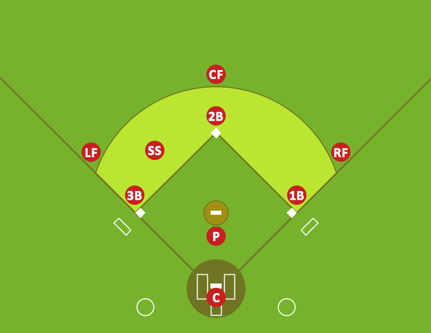
Example 1. Football solution
A combination of the "Football Fields" and "Football Positions" libraries gives you an ability to create a football-related drawing in seconds. Follow next steps to create you own football schema:
- From the "Football Fields" library drop a field object to your document
- From the "Football Positions" library drop all positions object you need to your document
- Place positions on the field according to your drawing idea
- Add arrows or text labels if needed.
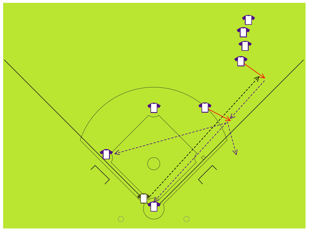
To display players moves use Connectors tool. On sample below we used Spline Connectors allows draw a freeform line depicts player moves close to reality. Then you are able to change Line Style, Line Weight, Line Color, and select Arrows on the ends.

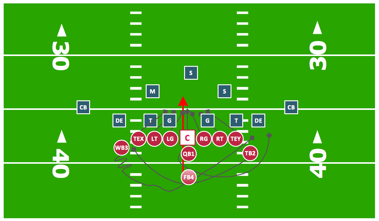
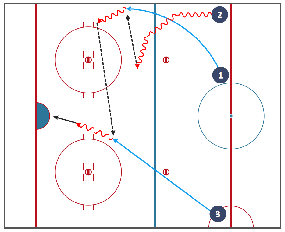
Example 2. Football — Offensive Play — Double Wing Wedge.
This diagram was created in ConceptDraw DIAGRAM using the "Football Fields" and "Football Positions" libraries from the Football solution. An experienced user spent 30 minutes creating this sample.
The samples you see on this page were created in ConceptDraw DIAGRAM using the Football Solution; they demonstrate a portion of the solution's capabilities and the professional results you can achieve.
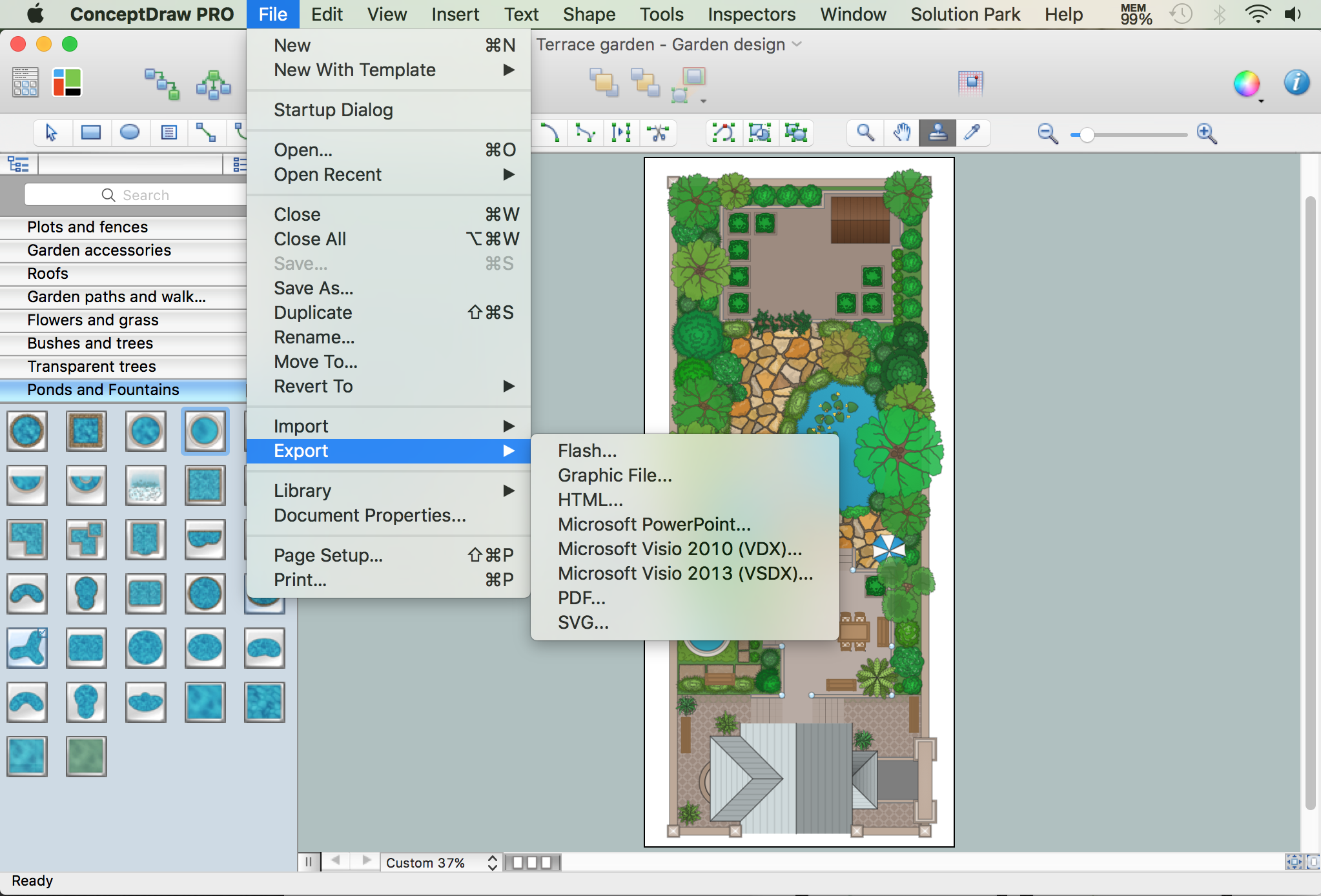
All source documents are vector graphic documents. They are available for reviewing, modifying, or converting to a variety of formats (PDF file, MS PowerPoint, MS Visio, and many other graphic formats) from the ConceptDraw STORE. The Football Solution is available for all ConceptDraw DIAGRAM or later users.