The Critical Path Method (CPM) is an algorithm for scheduling a set of project activities. It is an important tool for effective project management. implements this method to provide the user with a wide set of project management tools.
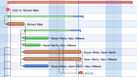
To display a critical path on the Gantt chart, open the View tab and check the Critical Path option in the Show/Hide section. Now you can see which tasks are most critical: the ones that add up to the longest project duration.
Pic. 1. Critical path on a Gantt chart.
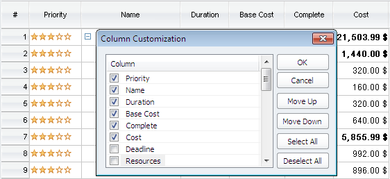
ConceptDraw PROJECT automatically calculates tasks’ Early Start, Early Finish, Late Start and Late Finish dates, as well as Early Slack, and Late Slack duration. To display these values, you should customize the columns in the table part of the window. Right-click (CTRL-click on Macs without a two-button mouse) on the project data column header, in the Column Customization window, select appropriate columns and click OK.
Pic. 2. Column Customization window.
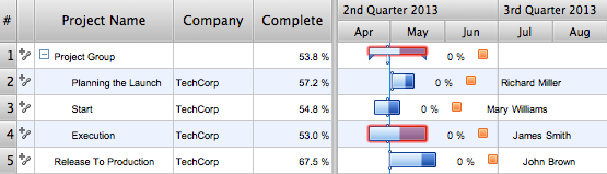
If you have a project that contains several related projects, you may need to determine their common critical path.To determine overall critical path, open the File menu and click Properties. In the Document Properties window open the Advanced tab and uncheck the Calculate independent critical path for each project option. You can also determine the slack time for tasks to be considered critical.
Pic. 3. Critical path on a Multiproject dashboard.
Video. Critical Path Method in ConceptDraw PROJECT
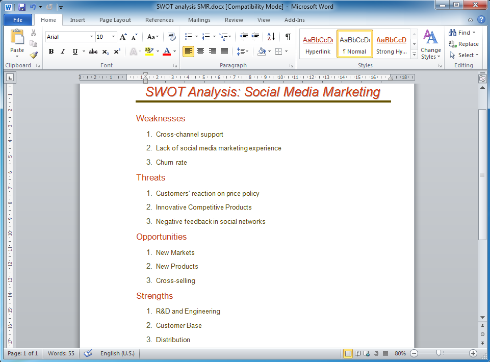
SWOT analysis is an effective method of business planning, the question is how to do it. The most obvious way is to make a SWOT analysis in a Word document, which is not very convenient. Luckily, you can use software like ConceptDraw DIAGRAM that has features and templates made especially for SWOT analyzing.
A SWOT Analysis is a manager's means of the strategic planning. It is used to define and classify considerable internal moments (strengths and weaknesses) and external forces (opportunities and threats) a business faces. You can use ConceptDraw MINDMAP to determine and organize factors utilized for SWOT analysis, and represent them in the SWOT matrix using ConceptDraw DIAGRAM. Using mind maps empowers you to explore and rank a lot of data engaged for SWOT analysis as well as recognize the relations between various pieces of information.
Picture: How to Make SWOT Analysis in a Word Document
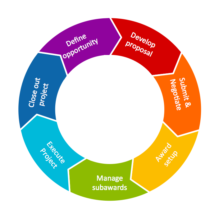
Circular Diagram is a type of diagram widely used in marketing and economics for visualization information in a clear and visual form. ConceptDraw DIAGRAM diagramming and vector drawing software offers the useful tools of the Target and Circular Diagrams solution from the Marketing area of ConceptDraw Solution Park for effective drawing a Circular Diagram of any complexity and design.
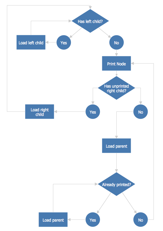
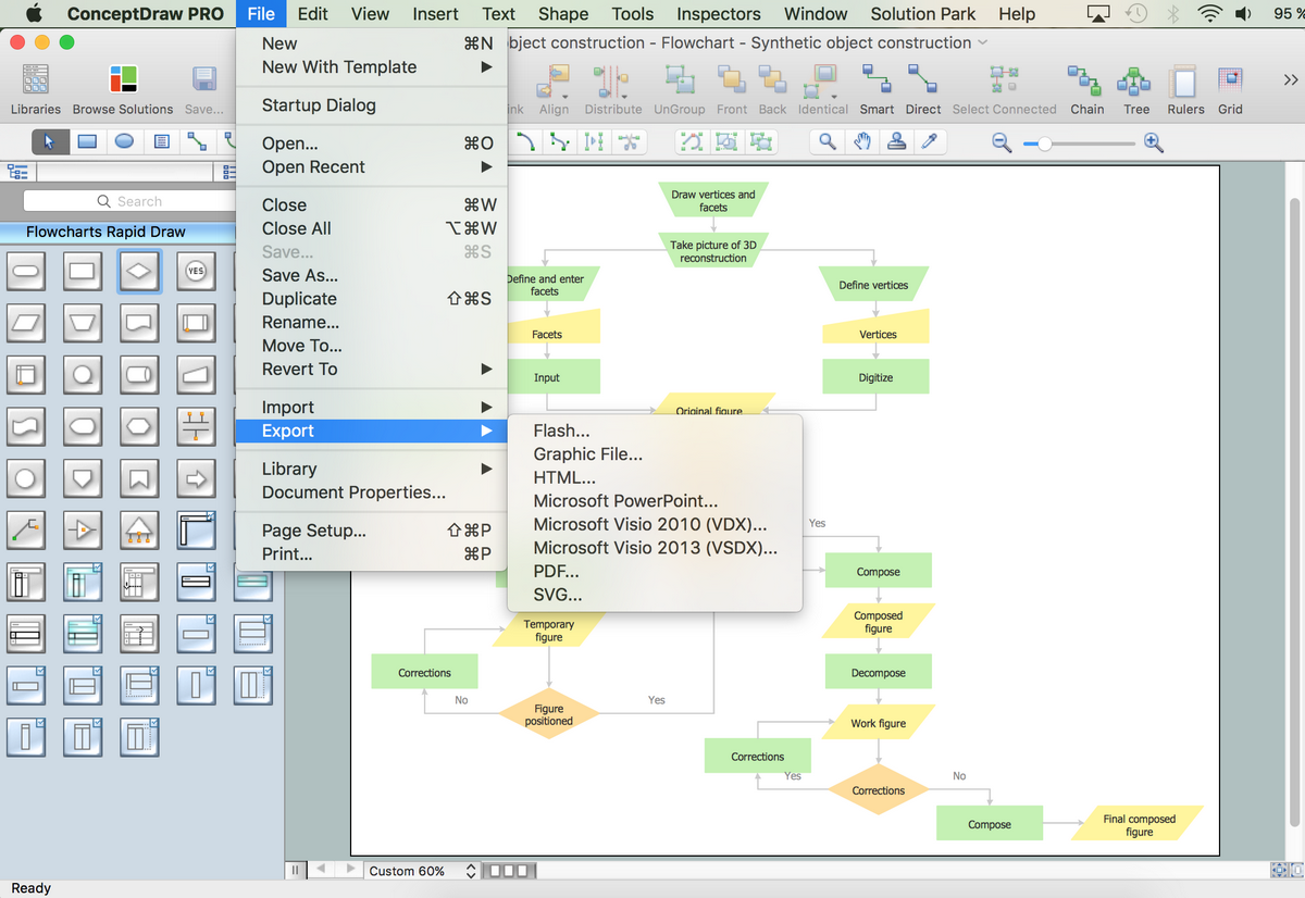
ConceptDraw DIAGRAM is a professional software for building of great-looking Flowcharts ✔️ of various types and any degree of complexity, ✔️ in a few simple steps, ✔️ even if you have no experience, ✔️ using RapidDraw technology, ✔️ to perform different tasks in different fields
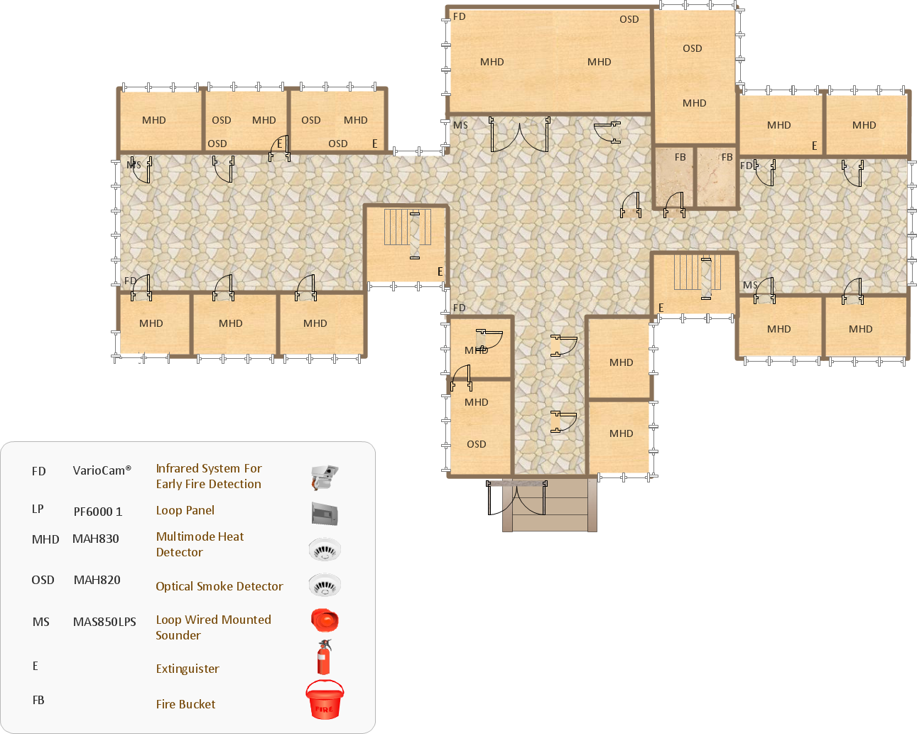
In the case of origin of an emergency is very important to have a correct, clear and comprehensible action plan which will help you to react quicker and to make right decisions. ConceptDraw DIAGRAM software extended with Fire and Emergency Plans solution from the Building Plans Area of ConceptDraw Solution Park provides extensive drawing tools for quick and easy creating fire and emergency plans, and also a set of various templates and samples, among them the Emergency Action Plan Template.
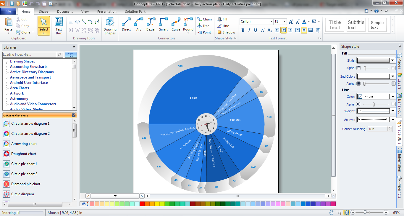
ConceptDraw DIAGRAM diagramming and vector drawing software extended with Target and Circular Diagrams solution from the Marketing area of ConceptDraw Solution Park is a powerful tool for Daily Schedule Chart design.
One of the stages of the problem's solving process scenario is Corrective Action Planning.
Corrective action planning define people and groups involvement in corrective actions by roles, identify logical sequences of scheduled actions and critical path of problem solving, identify possible risks of action plan and propose preventive actions.