Interaction Overview Diagram


UML Interaction Overview Diagram. Design Elements

ConceptDraw has 393 vector stencils in the 13 libraries that helps you to start using software for designing your own UML Diagrams. You can use the appropriate stencils of UML notation from UML Interaction Overview library.
Diagramming Software for Design UML Interaction Overview Diagrams

Software Defined Networking System Overview
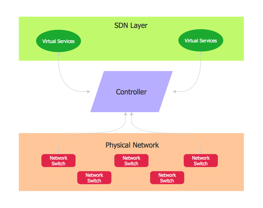
On this example you can see the Software-Defined Networking (SDN) diagram that was created in ConceptDraw DIAGRAM using the Computer and Networks Area of ConceptDraw Solution Park.

Introductory Guide to Rapid UML Solution

UML Diagram Types List

Data Flow Diagram Symbols. DFD Library

UML in 10 mins

This sample describes the credit card processing system. It’s a UML Class Diagram with generalization sets. This sample can be used by the banks, business and financial companies, exchanges.
How to create your UML Diagram

The 13 diagrams contained in the Rapid UML Solution offer an essential framework for systems analysts and software architects to create the diagrams they need to model processes from the conceptual level on through to project completion.
UML Use Case Diagrams

- UML interaction overview diagram - System authentication | Design ...
- Architecture Overview Diagram
- How To Draw System Context Diagram In Staruml
- System Overview Diagram Example
- Interaction Overview Diagram | Diagramming Software for Design ...
- Interaction Overview Diagram | Hostel Management System Project ...
- Interaction Overview Diagram | UML Collaboration Diagram ...
- Interaction Overview Diagram | Diagramming Software for Design ...
- Design elements - UML interaction overview diagrams | UML ...
- Bank UML Diagram | Interaction Overview Diagram | Process ...
- ERD | Entity Relationship Diagrams, ERD Software for Mac and Win
- Flowchart | Basic Flowchart Symbols and Meaning
- Flowchart | Flowchart Design - Symbols, Shapes, Stencils and Icons
- Flowchart | Flow Chart Symbols
- Electrical | Electrical Drawing - Wiring and Circuits Schematics
- Flowchart | Common Flowchart Symbols
- Flowchart | Common Flowchart Symbols